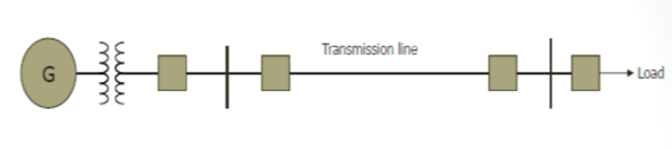
Transmission lines transports power from generating stations to load centre substations
Transmission lines operate typically from 33 kV lines up to 1100kV
Underground solid dielectric cables operate from lower voltages to sub transmission levels of 33 kV and higher voltages of say up to 230 kV
Oil filled cables operate up to 500 kV
Inductance of a Transmission Line
Inductance of a Transmission Line
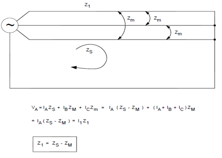
Mutual impedance between parallel conductors (with earth return path)
Self Impedance
Carson’s equation for impedance of line with earth return is as below.
Zs = Rc + Rd +j0.004657f*log[De/GMR]
Where:
Rc is the conductor resistance (AC resistance is in ohm/mile)
Rd is the earth resistance (1.588*10^-3*f Ohm/mile)
De equivalent spacing of the earth return path=De = 2160*Sqrt (Soil Rho/f) feet
GMR = Geometric Mean Radius (0.778 times the actual radius for a solid conductor)
Self Impedance At 60 HZ
Zs = Rc+ 0.09528 + j0.2794log[De/GMR] Ohm /mile
Soil Earth Resistivity =Rho in Ohm-m
Average damp earth Rho is 100 ohm-m Swamp-10-100 ohm-m & Sand stone = 109 ohm-m
De = 2790 with average damp earth
Mutual Impedance
Zm = 0.09528 + j0.2794log[De/D] Ohm/mile
D = distance between two circuit conductors
POSITIVE SEQUENCE IMPEDANCE
ZERO SEQUENCE IMPEDANCE
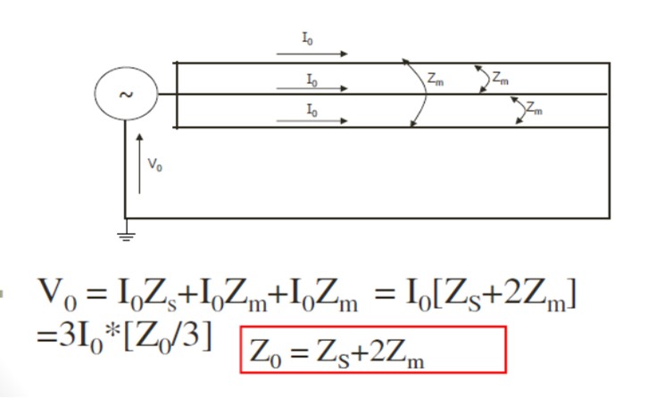
SELF & MUTUAL IMPEDANCE
ZS = Z1+Zm = Loop Impedance
= Pos.Seq Impedance + Ground Impedance
Z1 = Zs – Zm
Z0= Zs + 2 Zm
Loop Impedance = Zs = Z1 + Zm =Pos Z + Ground Z
Zo = Z1 + 3 Zm. Hence Zm = (Z0-Z1)/3
Ground Z = Zground = Zm = (Z0-Z1)/3 = K0Z1
Where
K0= (1/3) * [Z0-Z1] / Z1
K0 is Zero Sequence compensation factor.
ZS = Rc+0.09528+j0.2794log[De/GMR]Ω/mile
Zm=0.09528+ j0.2794log[De/GMR]Ω/mile
Z1 = Zs-Zm=Rc+j0.2794log[D/GMR]Ω/mile
Positive sequence impedance is not dependant on the earth resistivity and the fictitious earth return path.
It does not depend on the height of the conductor from the ground.
ZERO SEQUENCE IMPEDANCE
- At 60 Hz;
- ZS = Rc+0.09528+j0.2794log[De/GMR] Ω / mile
- Zm=0.09528+ j0.2794log[De/D] Ω/mile
- Z0 = Zs+2Zm
- =RC+0.19056+j0.2794log[De3/(GMR*D2)] Ω/mile
- Zero sequence impedance is dependent on the earth resistivity and the fictitious earth return path.
LINE PROTECTION
Differential Schemes
Compare currents at two ends of the line
Non-Unit protection
Detects faults based on measurement at one end:
Overcurrent or impedance based protection
Current based schemes
Requires a communication channel to exchange information between two ends.
Communication channels:
Pilot wire
Leased telephone line
Microwave communication / Radio
Optical fiber
Power line carrier
Reliability depends on the communication channel availability.
Speed depends on the communication channel
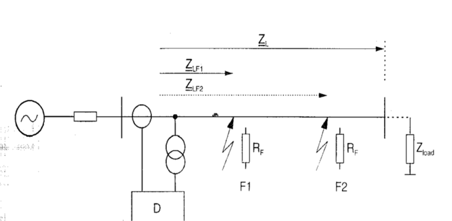
Distance Protection
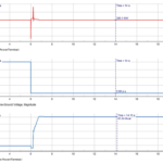
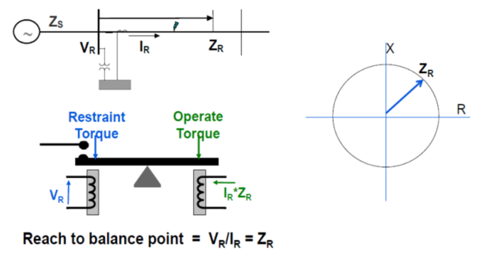
Distance protection determines the fault impedance from measured short circuit voltage and measured short circuit current at the relay location.
The measured fault impedance is then compared with the known line impedance.
If the measured fault impedance is smaller than the set line impedance, an internal fault is detected and a trip command is issued to the circuit breaker.
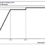
Due to inaccuracies in distance measurement resulting from CT VT errors and inaccuracy of line impedance, a protection reach setting of 100 % of line length with a distance zone is not possible in practice.
A security margin of 10 to 15 to 20 % from the remote line end must be selected for the so called under reaching stage Zone 1 to ensure secure protection selection between internal and external fault.
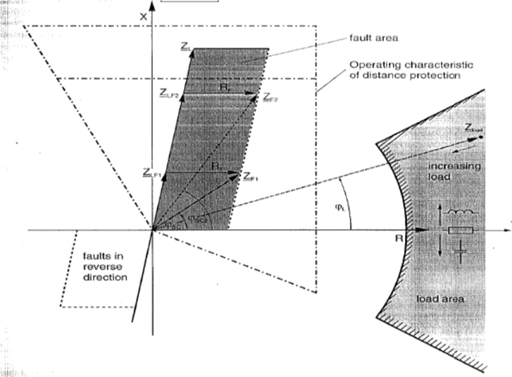
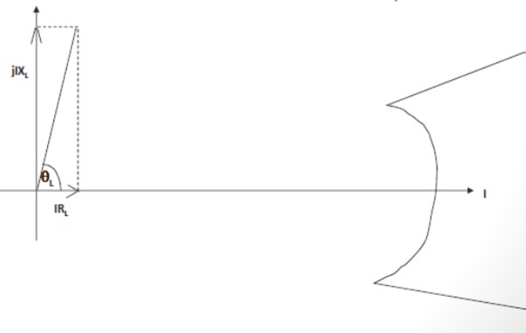
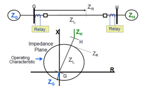
Impedance Diagram ( R-X diagram in R-X Plane)
For distance protection impedance diagram is the most essential tool for evaluation of behaviour of distance protection
In R-X diagram the distance relay characteristics, the line impedance, the fault impedance, load impedance are plotting on a common complex R-X plane
Relationship of all these on R-X diagram gives indication of relay performance
Distance Protection Load Impedance
Load and SC Impedance & Relay Characteristics On Common R-X Diagram
During normal operation the measured impedance corresponds to load impedance
Its magnitude Z load = kVLL^2 / P load
Its magnitude Z load = kVLL^2 / P load
After inception of fault, the measured impedance reduces from load to short circuit impedance which corresponds to impedance of section of line between the relay and fault location
After inception of fault, the measured impedance reduces from load to short circuit impedance which corresponds to impedance of section of line between the relay and fault location
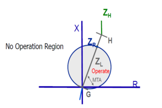
The operating characteristic of distance relay, which is a fixed characteristic based on relay characteristic selected, is added in the R-X diagram along with Line fault impedance, arc resistance and load impedance
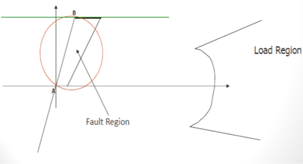
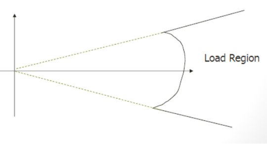
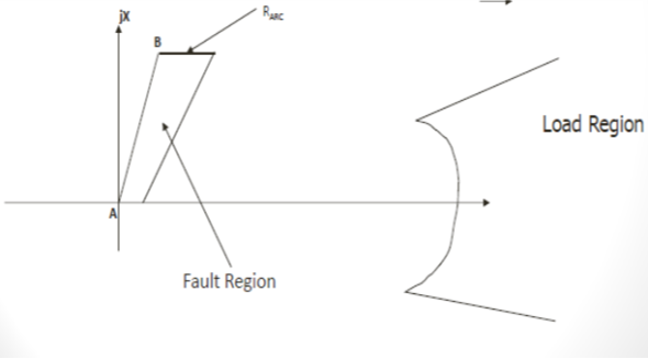
The R-X diagram clearly shows the fault area the relay characteristics area and the load impedance area and shows whether load area encroaches or not into the arc resistance area and whether safe margin is available between them
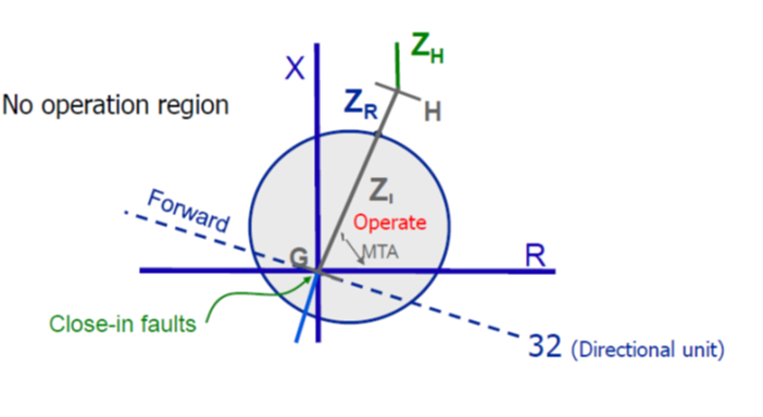
The R-X diagram includes the directional characteristics that defines two impedance areas by means of which the relay establishes whether fault is in the forward or reverse direction
Representation of a system on R-X diagram
LOAD CHARACTERISTICS
Load – Mostly Resistive;
0.8 Leading Power factor [-37 degree]
0.8 Ladding power factor [+37 degree]
Arc Characteristics is Resistive
Constant Voltage drop
440V/ft –Westinghouse Formula.
Westinghouse Formula:- R = 440*L/I
Arc Resistance As Per Warrington Formula
R = 8750* (L+3Ut)/ I^1.4
Where L is the length of the arc in feet,
U is the wind velocity in mph,
t time in seconds.
Warrington Empirical formula for arc resistance for arc length in metre
Ra = (28710 * L) / (I ^ 1.4)
Ra = arc resistance (ohms)
L = length of arc (metres)
I = arc current (A)
Load Region- Fault Region R-X Diagram
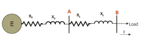
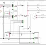
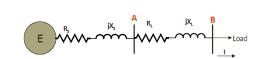
Voltage and current inputs as in SLD below
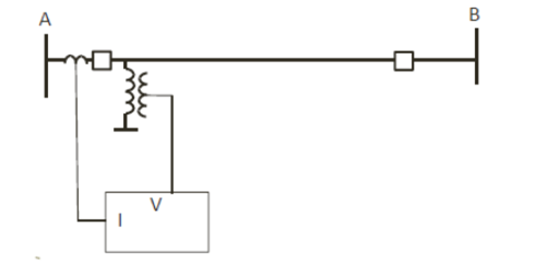
Uses both voltage and current to determine if a fault is within the relay’s set zone of protection Settings based on positive and zero sequence transmission line impedance Measures phase and ground fault loops.
Primary and Secondary Impedance
Primary line impedance, ZLPRI
Relays are connected to the secondary of Potential Transformers (PT) and Current Transformers(CT)
ZSEC = VSEC/ISEC
ZSEC = [VPRI/PTR]/[IPRI/CTR]
Since
VSEC = VPR/PTR
ISEC = IPR/CTR
ZSEC= [VPRI/ IPRI]*[CTR/PTR]
ZSEC = ZPRI* [CTR/PTR]
Simple Balanced Beam
IMPEDANCE DISTANCE CHARACTERISTICS
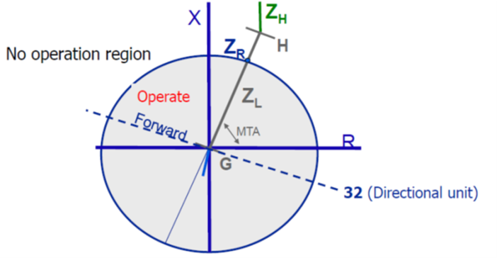
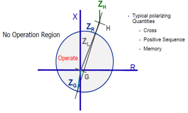
Mho Characteristics
Mho distance, self (fault voltage) polarized
Mho distance, healthy voltage polarized Off set Mho characteristics
OFFSET MHO DISTANCE
Motor Contactor Rating
Contactor cannot break fault kA, but it can break kA of 8-10 times its rating.
Earth fault (E/F) relay operates to open the contactor at kA greater than the contactor interrupting capability.
Reactance Relay Characteristics
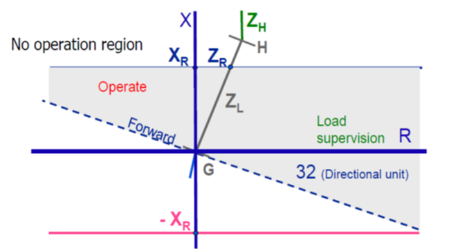
QUADRILATERAL CHARACTERISTICS
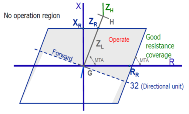
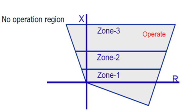
STEPPED ZONE QUADRILATERAL DISTANCE PROTECTION APPLICATION
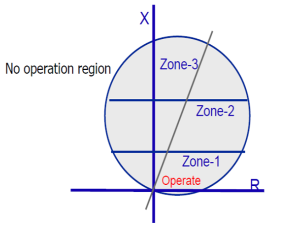
REACTANCE WITH MHO DISTANCE RELAY CHARACTERISTICS
Lenticular characteristic
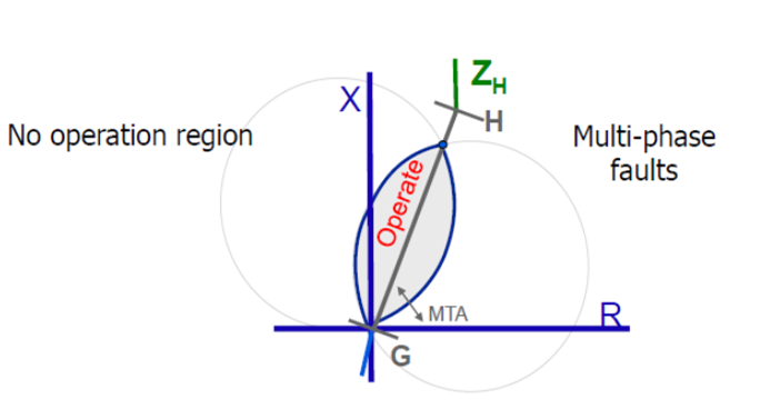
Application- Impedance relay characteristics
Distance Relay Characteristics
Impedance Relay
Mho Relay
Reactance Relay
Quadrilateral