Relay Design
The relay compares phase angle between two voltage signals
The relay design is analyzed in next few slides by considering following three fault conditions
F1- fault beyond the relay reach
F2 – fault inside the relay reach
F3- fault behind the relay location- reverse fault
The relay operates and trips (opens CB) the line only if the measured impedance is less than or equal to setting of ZL.
RELAY CHARACTERISTICS

Protected Line – A-B; Impedance ZL (referred to the Secondary of CT and PT)
Relay location –A Set to detect faults up to B
Fault f1, f2 are in front of the relay
Fault f1 is outside the line section A-B
Fault f3 is behind the relay
Fault at f1 – External to the line section A-B

ZL1 >ZL ;
Relay input: voltage V and Current I
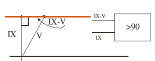
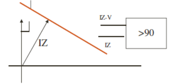
V-IZL and V are in phase
Relay is set to block if V and V-IZL are in phase
Fault at f2 – internal to the line section A-B


ZL2 <ZL ;
V-IZL and V are 180 egree out of phase
Relay is set to trip
if V and V-IZL are 180 degree out of phase
Fault at f3 – Reverse fault-external to the line section A-B


ZL2 <ZL (or ZR);
Relay input: voltage V and Current I
V-IZL and V are in phase
Relay is set to block if V and V-IZL are in phase
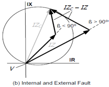
Relay – Phase comparator


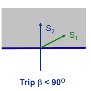
Trip if :=
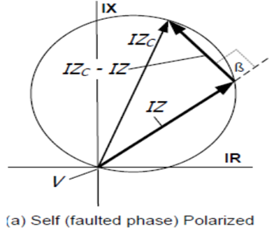
Angle between S1 – V and S2=V-IZC > 90 degree
V is Vf at relay and I = If at relay
Z = Zf=fault impedance
Zc is characteristic setting reach of relay
Relay – Phase comparator

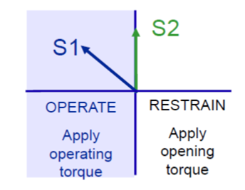
Relay – Phase comparator-SELF POLARISED MHO

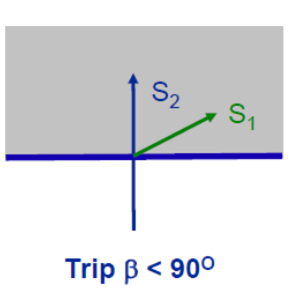
Relay – Phase comparator
Mho distance phase comparator – cross polarized

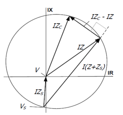

Characteristic Angle
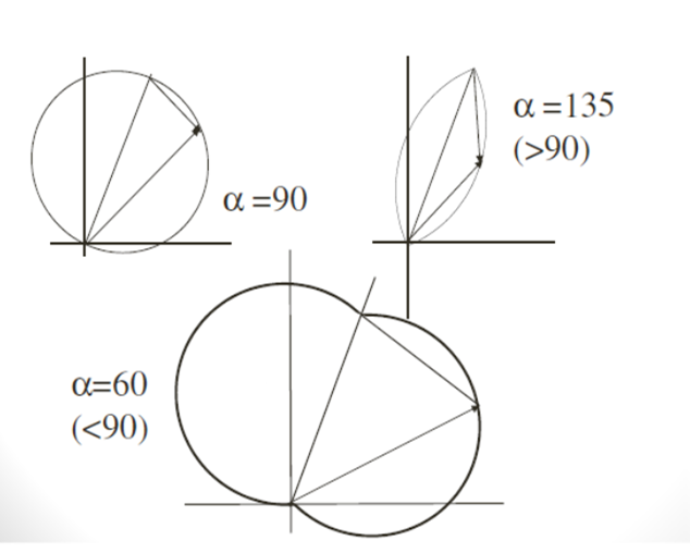
OTHER CHARACTERISTICS
REACTANCE
OHM:-
Types of Faults in Three Phase System
Phase to ground faults- A-G,B-G,C-G
Phase-Phase faults – A-B, B-C, C-A
Phase to phase to Ground –A-B-G, B-C-G,C-A-G
Three phase fault with/ Without Ground
Cross Country faults – Two single line to ground faults on different phases and at Different locations
Relay(Comparator) Inputs
The goal is to measure the same impedance up to the fault point irrespective of the type of fault

Relays measure the positive sequence impedance of the line up to the fault point
Phase to ground distance elements
A-G Fault : VA and IA + K0*IN
B-G Fault ; VB and IB + K0*IN
C-G Fault : VC and IC + K0*IN
Phase – Phase Fault
A-B Fault : VAB and (IA-IB)
B-C Fault : VBC and (IB-IC)
C-A Fault: VCA and (IC-IA)
Total distance elements (units)
Six distance elements are needed to detect all types of faults.
Apparent impedance of fault loops
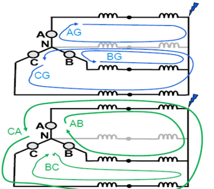
6 fault loops measured for each zone fault Types
Phase-to-ground
Phase-to-phase
Two phase-to-ground
Three phase
Apparent impedance of fault loops
Phase-to-phase
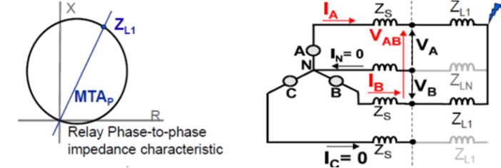

Apparent impedance of fault loops
Phase-to-ground


Apparent impedance of fault loops
Phase-to-ground. For Ph-E fault on phase-A
The voltage Va at relay point is
Va= Ia1 Z1 + Ia2 Z2 + Ia0 Z0
If Z1 = Z2, then
Va= Ia1 Z1 + Ia2 Z1 + Ia0 Z0
The current Ia at relay point is
Ia= Ia1 + Ia2 + Ia0
The Residual current at relay point
In = Ires = Ia + Ib + Ic = 3 * Ia0
If Z1 = Z2, then
Va= Ia1 Z1 + Ia2 Z2 + Ia0 Z0
Va= Ia1 Z1 + Ia2 Z1 + Ia0 Z0 + IaoZ1 – IaoZ1
Va= Z1 * ( Ia1 + Ia2 + Ia0 ) + Iao * (Z0 – Z1)
Va= Z1 * ( Ia ) + Iao * (Z0 – Z1)
Va= Z1 * [ Ia + Iao * (Z0 – Z1)/Z1 ]
Va= Z1 * [ Ia + 3Iao * (Z0 – Z1) / 3Z1 ]
Va= Z1 * [ Ia + 3Iao * (Z0 – Z1) / 3Z1 ]
Va = Z1 ( Ia + 3 Ia0 (Z0 – Z1)/3Z1)
Va = Z1 ( Ia + KN * Ires)
Where, Z1 = Va / ( Ia + KN* Ires) & And KN = (Z0 – Z1)/3Z1
Phase-to-ground


TWO FACTORS USED FOR I0 ZERO SEQUENCE COMPENSATION
VA= ZL1 & [ IA +KN*Ires ]


Ground Reach is set in Terms of ZL1 & KN
ZG=ZL1*(1+KN)

