Errors in line impedance measurement
- Instrument transformer Errors
- CT errors and PT errors
- Relay design tolerance
Line impedance calculation errors
Relay with reach setting ZAB for line between stations A & B may operate for faults beyond bus B
The relay is set to operate without any delay for faults up to 80-85% of the protected line section impedance, ZAB. This is also called Under reaching zone or Zone1
15-20% of the remaining line section is protected by a second set of relay. These relay zone is set to reach 20-25% beyond the bus B. This is also called Overreaching Zone or Zone 2.
The Zone 2 tripping is always time delayed to coordinate with remote end breaker and line relays
Zones of Protection
Stepped Distance Scheme
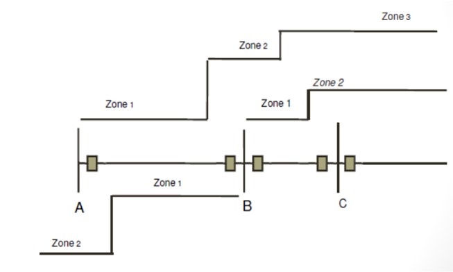
Zone 1(Under reaching Zone)– Typically set to 80-85% of the protected line impedance. This conservative approach prevents relay from operating for faults beyond the line section
Zone 2(overreaching Zone) – At least 115% of the line impedance to account for errors. – typical setting; 125-150% of the protected line impedance.
Zone3 (Over reaching Zone) – Typically to cover 125- 150% of adjacent line
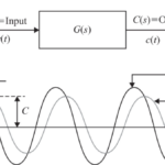
Apparent Impedance (Infeed Under Reach Effect)
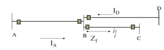
Impedance Seen by Relay at ‘A’ is ZAf = ZA+Zf
Voltage at ‘A’ =I IA*ZAB + [IA+ID]*Zf ]
ZAf = V at ‘A’ / IA
= ZAB + [1+ ID / IA]*Zf
= ZA + Zf + [ ID / IA]*Zf
Impedance seen by the relay > actual impedance to the fault point.
The relay under reaches since this effect reduces the apparent reach measured by distance relays
Impedance seen by the relay at ‘D’
= ZBD + Zf +[IA / ID]*Zf
A distance relay is said to under-reach when the impedance presented to it is apparently greater than the impedance to the fault
Percentage under-reach is defined as:
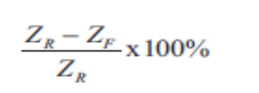
where:
ZR = intended relay reach (relay reach setting)
ZF = effective reach
Zone 2 i.e Z2 at A must be set to overreach bus B for in_feed at bus B and not to overreach bus D for no in_feed at bus B
Out_feed Overreach Effect
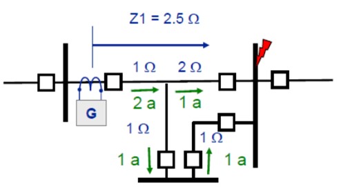
Usually associated with three terminal line applications and paralleling of line segment
Example as in above SLD:
VG = 2(1) + 2(1) = 4
ZG (Apparent) = VG / IG
ZG = 4/2 = 2 Ohm
Z1 will overreach and see the fault
A distance relay is said to over-reach when the impedance presented to it is apparently less than the impedance to the fault
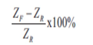
where:
ZR = intended relay reach (relay reach setting)
ZF = effective reach
Tapped transformers and loads Under reach effect
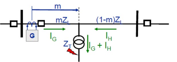
VG = IG*mZL + ( IG + IH ) ZT
ZG (Apparent) = VG / IG
ZG = m*ZL + (1 + IH/IG) ZT
ZG = mZL + ZT + IH/IGZT (Increase in apparent impedance)
Apparent impedance will always be larger than impedance to fault.
Relay at G will under reach.
Lines terminated into transformers
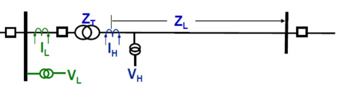
IH and VH preferred to provide line protection
Use of VL and/or IL affects measured impedance and requires CT and/or VT ratio adjustment
Transformer should always be protected separately
Source impedance ratio
Ratio of source impedance to the line impedance
SIR to the relay is the ratio of source impedance to the zone impedance setting
The higher the SIR the more complex the line protection with zone 1
Measurement errors are more pronounced Current and or voltage transformer error CVT transients
Zone-1 may not be recommended in many applications and Current differential protection preferred
Switch onto fault logic
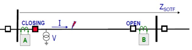
Logic determines breaker has been open awhile and sets SOTF logic (aka: CIFT, SOFT)
- Breaker position
- Dead line logic
When breaker controlled by relay A closes SOTF asserts when:
I and Not V, and/or SOTF operates
Set ZSOTF offset, overreaching line and below minimum load impedance
Three Terminal line Application
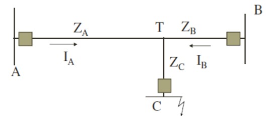
Zone 1 at A- 85% of the shorter line section 85% of Minimum of ZAB or ZAC
Zone 2 at A – 125% of the apparent impedance of the longest line section or
ZA + 1.25*ZC_apparent or 1.25(ZA + ZC_apparent)
=1.25*[ ZA +ZC(1 +IB/IA)]
Time Coordination
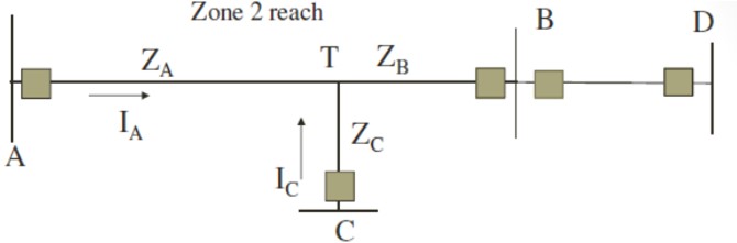
Relay at A: Zone 2- 125% ZAPP
Zone 2 = 1.25*[ZA+ZB*(1+IC/IA)]
Relay at B on B-D line:
Zone 1 -85% of ZB-D
When there is no infeed (breaker C open), the zone 2 relay reaches beyond terminal D
Zone 2 time delay needs coordination with relays at B on line B-D
Sequential Tripping

If the ratio of currents is high – ex-20:1 for IC/IA
Relay at A sees ZA+ZC(1+20)
Relay setting is too large
Allow stronger end ( End- C in this case) to trip first
Relay at A operates after breaker at C opens
Zone 2 or Zone 3 Settings
Overreaching zones should consider apparent impedance (Z2 for three terminal line)
Zone 3- 100% of the line +125% of apparent impedance of adjacent line
If it is not possible to set, sequential tripping could be utilized
Factors that influence Distance Relay settings & operation
Parallel Lines – Effect of Mutual impedance on ground distance elements
- Current Reversal
- Series compensated lines
- Effect of load
- Out of Step condition
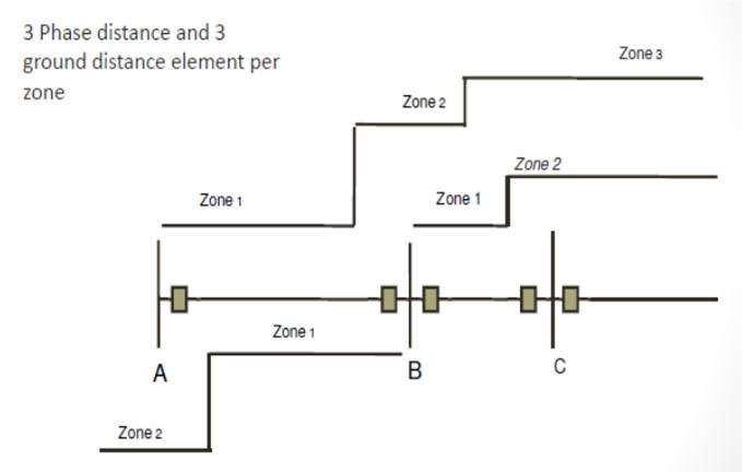
Phase distance and Ground Distance Schemes
3 Phase distance and 3 ground distance element per zone
Phase distance & Ground overcurrent Schemes
Distance Elements to detect phase-phase and three phase faults
Ground directional overcurrent relay to detect faults involving ground
Zone coordination using distance & ground relays
Distance zones are time coordinated based on reach
Ground overcurrent relays (directional inverse time overcurrent relays) are also coordinated with time.
Fault clearing times on lines
Z1- Distance – Assume Zone 1 setting = 85% of line Z
All faults within 15-85% of the line are cleared by both end without any time delay.
Remote end faults (85-100% from end A) – cleared by Zone 2 with a time delay (typically 15-30 cycles)
Close-in faults (0-15%) from end A are cleared in zone 2 from line relay at end B
End-Zone Faults
0-15% from ends are cleared in zone 2 from remote ends
These are called end-zone faults
Total fault clearing time is equal to zone 2 time delay + breaker operating time
Pilot Schemes
- Phase comparison Scheme
- Current differential schemes
- Directional Comparison schemes using distance (or directional over current) relays
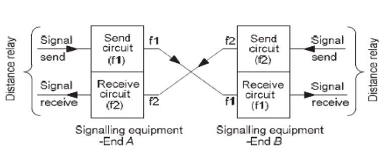
Communication Medium
- Power line Carrier
- Leased telephone line
- Microwave
- Fiber optic cable
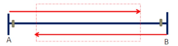
Directional Comparison Scheme
Uses directional relays to determine fault position relative to the protected line and communicates that information to the remote terminal
The information is used to achieve faster tripping at both ends.
Terminology
ZUR -Underreaching Zone (Element) – Relay set to reach shorter than the total protected line
ZOR – Overreaching Zone (Element) – Relay set to reach longer than the total protected line
Various tripping schemes were originally designed with electromechanical relays and had distinctive names
Microprocessor relays combine various schemes with same nomenclature
We will use Z1 for the ZUR and Z2 for ZOR
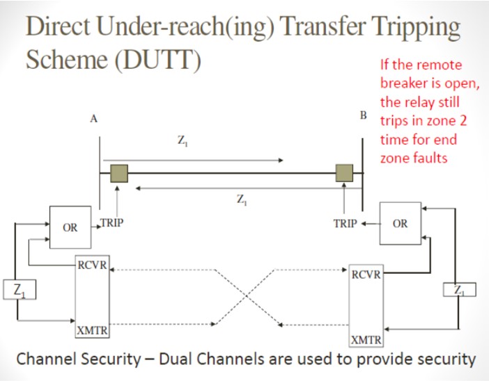
Direct under reach transfer trip transfer
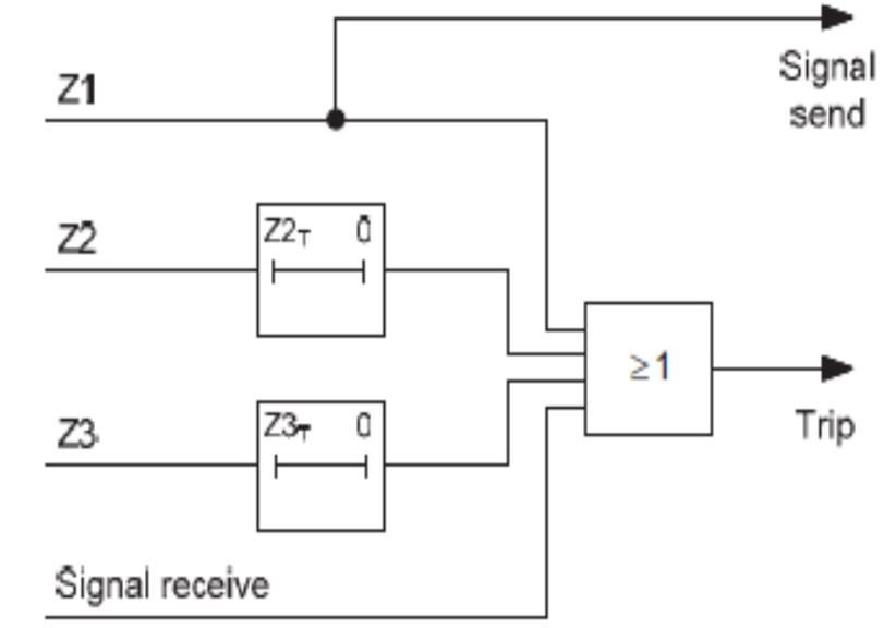
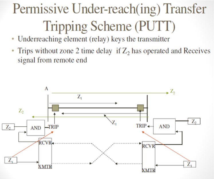
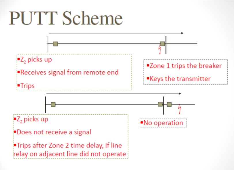
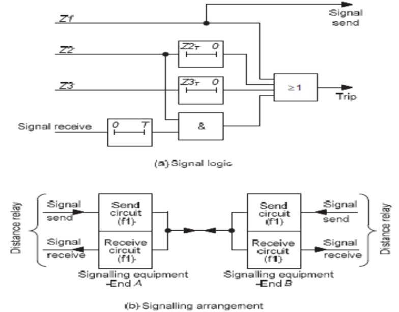
Permissive under reach transfer trip transfer
Issues With permissive under reach transfer trip transfer For single-end fed close-up fault on double circuit line
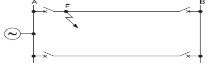
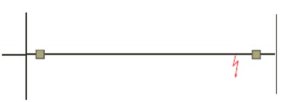
Fault occurs close to A as shown. Bus A voltage low so negligible fault infeed from B end
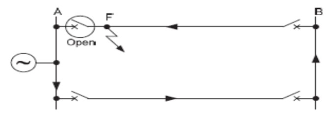
End A CB Clears Fault and fault is then fed from end B
Issues With permissive under reach transfer trip transfer For single-end fed close-up fault on double circuit line
Time delayed resetting of the PUR ‘signal received’ element is required (because other wise both zone1 at source end A and received signal at B end would reset before fault reverses and Zone 2 at B end operates)
Time delayed resetting of received signal is required to ensure that the relays at both ends of a single-end fed faulted line of a parallel feeder circuit have time to trip when the fault is close to one end
Time delayed resetting of the PUR ‘signal received’ element
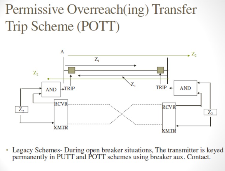
PERMISSIVE OVER REACH TRANSFER TRIP SCHEME
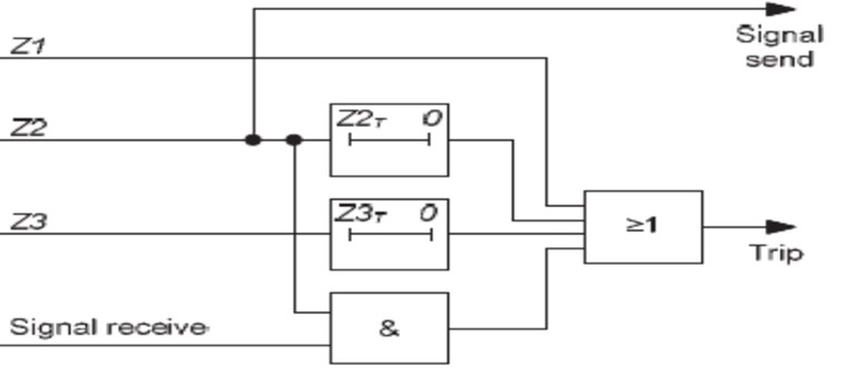
PERMISSIVE OVER REACH TRANSFER TRIP SCHEME CURRENT REVERSAL GUARD IN PARALLEL DOUBLE END FED LINES WHERE ZONE 2 REACH IS SET GREATER THAN 150 % OF PROTECTED LINE
To prevent operation under current reversal conditions in a parallel feeder circuit, a current reversal guard timer to is required to inhibit the tripping of the forward Zone 2 elements.
Otherwise maloperation of the scheme may occur under current reversal conditions
PERMISSIVE OVER REACH TRANSFER TRIP SCHEME CURRENT REVERSAL GUARD IN PARALLEL DUAL END LINES
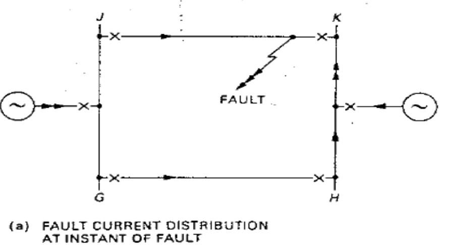
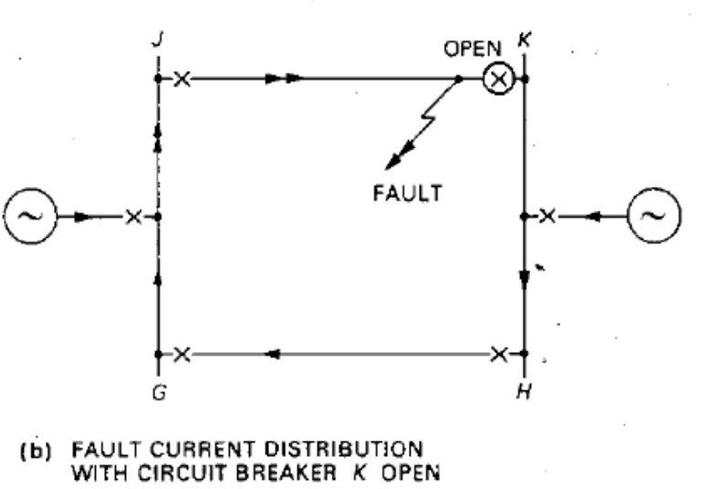
For fault close to K end, protection at K clears fault faster than at J.. As soon as K end CB opens, the direction of current in healthy feeder reverses. The Zone 2 at end G of healthy feeder had OPERATED and had send signal to H when fault at K started gets RESET when breaker at K opens to clear fault end H of healthy feeder that had RESTRAINED when fault at K started OPERATES when breaker at K opens to clear fault near it
If Zone 2 at H operates before Zone 2 at end G resets tripping of breakers on healthy feeder at G & H takes place. This is not a desirable tripping
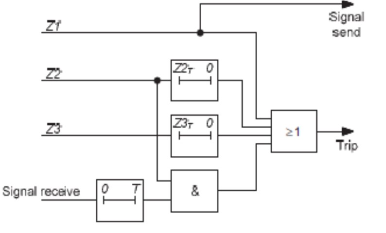
The timer is used to block the permissive trip and signal send circuits as shown in next slide. The timer is energised if a signal is received and there is no operation of Zone 2 elements.
An adjustable time delay on pick-up (tp) is usually set to allow instantaneous tripping to take place for any internal faults, taking into account a possible slower operation of Zone 2. The timer will have operated and blocked the ‘permissive trip’ and ‘signal send’ circuits by the time the current reversal takes place.
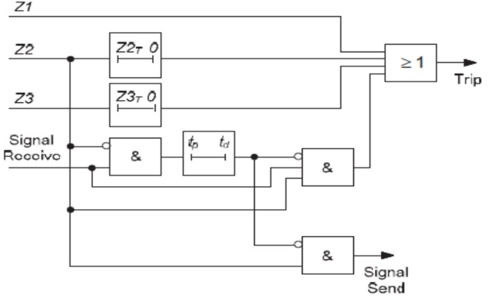
Current reversal guard logic – permissive over-reach scheme
Weak Infeed Conditions
In the standard permissive over-reach scheme, as with the permissive under-reach scheme, instantaneous clearance cannot be achieved for end-zone faults under weak infeed or breaker open conditions.
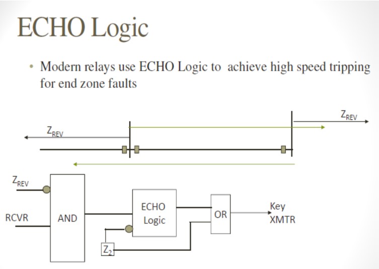
The Weak Infeed Echo feature available in some protection relays allows the remote relay to echo the trip signal back to the sending relay even if the appropriate remote relay element has not operated.
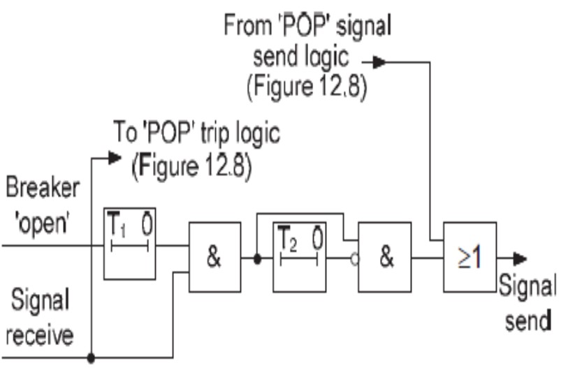
A time delay (T1) is required in the echo circuit to prevent tripping of the remote end breaker when the local breaker is tripped by the busbar protection or breaker fail protection associated with other feeders connected to the busbar.
The time delay ensures that the remote end Zone 2 element will reset by the time the echoed signal is received at that end.
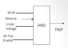
A variation on the Weak Infeed Echo feature is to allow tripping of the remote relay under the circumstances described above, providing that an under voltage condition exists, due to the fault
Weak Infeed Trip feature and ensures that both ends are tripped if the conditions are satisfied.
Reverse Looking Zone
Could be Zone 3 or Zone 4 depending on the manufacturer
POTT logic is designed in the relay based on zone 3 or zone 4
GE- Zone 4 is the reverse looking element
SEL – Zone 3 is the reverse looking element
Reverse element is set to reach farther than the remote overreaching element (Zone 2)
If there is no current flowing on the line, Voltage at the fault will be same as the voltage at the relay.
If the system is not weak, Voltage at the relay location will be more that the voltage at the fault location.
The U/V setting has to be below the voltage seen under normal condition.