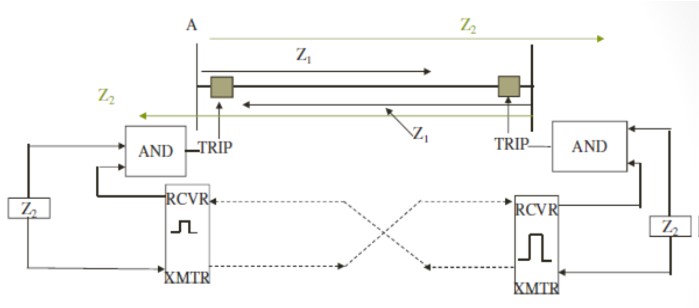
Hybrid POTT
GE Called a scheme with ECHO logic and Reverse looking elements as Hybrid scheme.
SEL calls this POTT scheme
Directional Comparison Unblocking Scheme DCUB
This is a permissive scheme (POTT)
Uses frequency shift carrier communication
Since the signal is transmitted on a faulted line, the tripping is permitted for 150ms if the carrier signal is lost during a fault
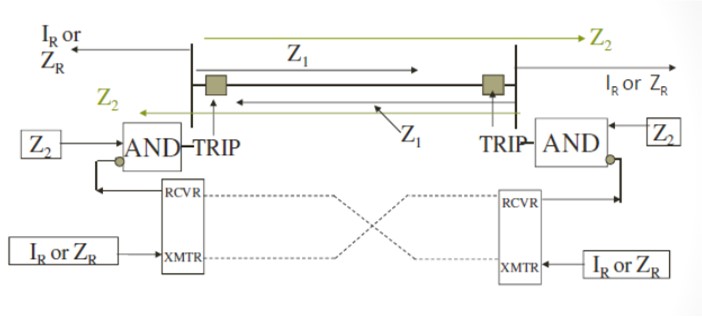
DCUB
Receiver produces a pulse on loss of signal
This logic can also be programmed in the relay
Loss of signal information is connected as input to the relay
Directional Comparison Blocking Scheme -DCB
The relay information is transmitted to the remote end only if the fault is not on the protected line
Reverse looking relays key the transmitter.
Zone 2 element waits for a blocking signal from remote end for a short period 1-2 cycles
Trips bypassing the zone 2 timer if no blocking signal is received.
If blocking signal is received, the tripping is via the zone 2 timer
DCB scheme
ON/OFF Carrier is used
Distance Protection Power Swing Detection & Blocking
Pole-slip and power swing protection relays measure the impedance trajectory of the network to detect a pole slip or power swing
An expression for the swing impedance is derived by using the basic network
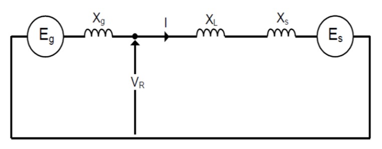
Equivalent circuit to derive the swing impedance
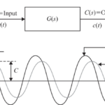
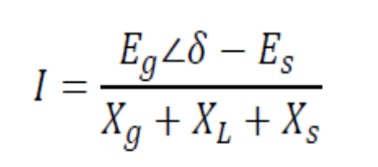
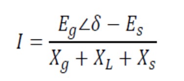
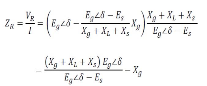
If Es is reference and let Eg is in phase advance ahead of Es by angle δ, the current measured by the protection relay at the generator terminals:
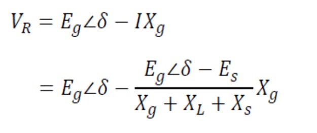
The voltage seen by the protection relay at the generator terminals:
The impedance measured by the protection relay at the generator terminals:
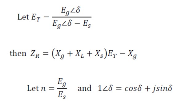
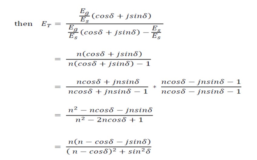
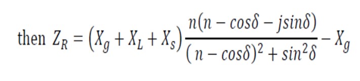
Where n = Eg / Es
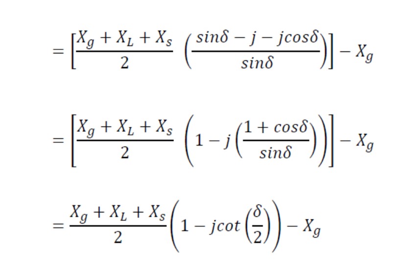
The impedance measured by the protection relay at the generator terminals (where n = Eg/Es = 1)
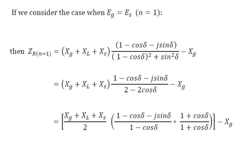
Distance Protection Power Swing Detection & Blocking
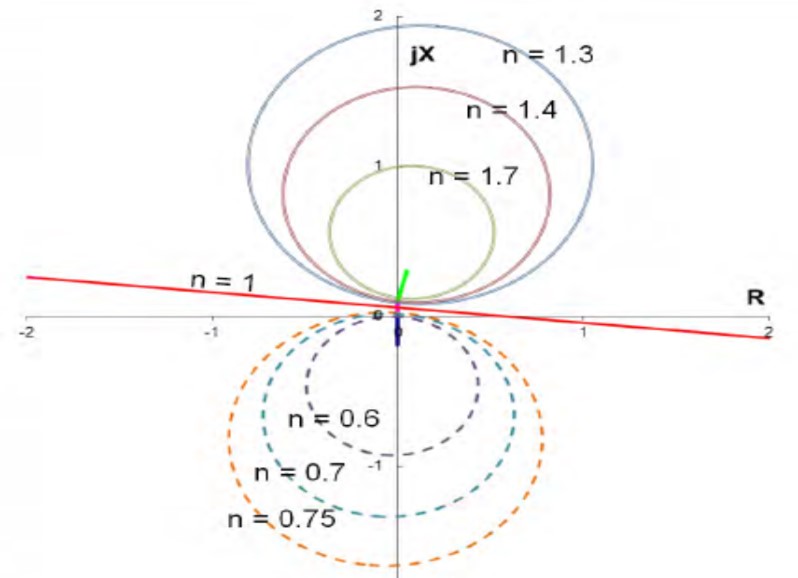
Swing impedance for n = 1 & n < 1 & n > 1
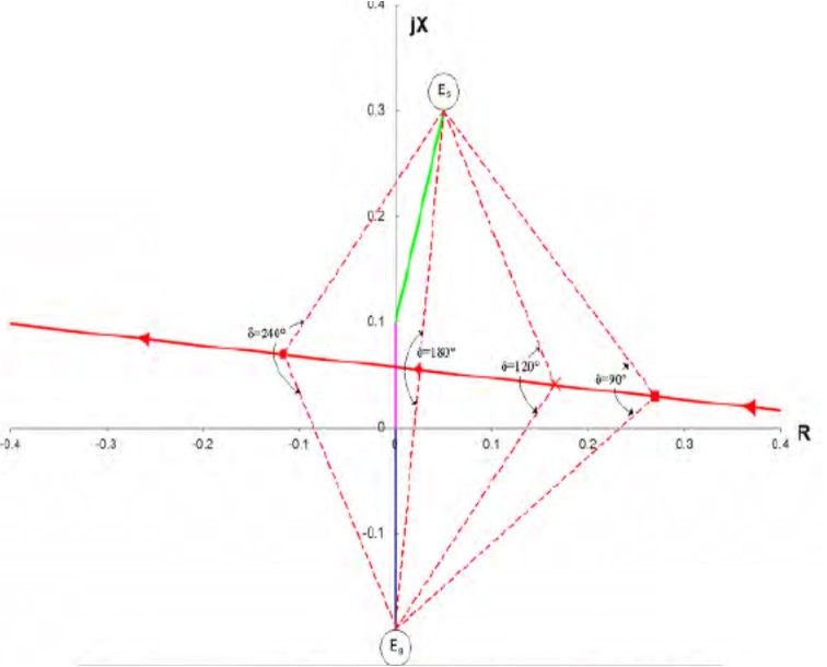
Swing impedance when n=1 (Eg = Es)
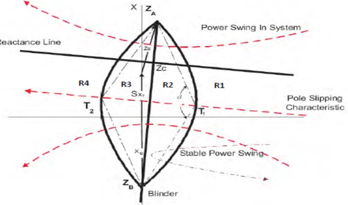
Typical Power Swing Or Pole Slip Tripping Relay
The pole-slip impedance characteristic of the typical make of relay is as shown
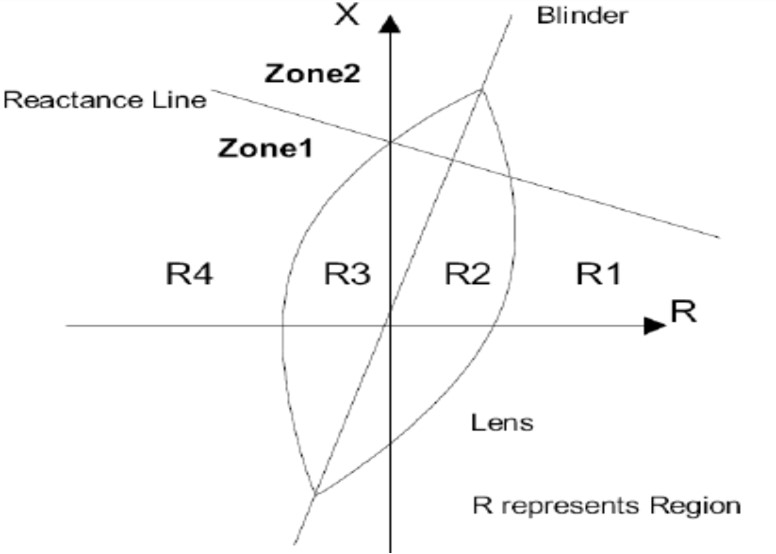
The detecting elements of the relay consist of a lenticular (lens) impedance characteristic and a single straight line blinder that bisects the lens characteristic into two equal parts
The third part of the characteristic is a reactance line that divides the characteristic into two zones namely zone 1 and zone 2.
Zone 1 would usually be used to detect a pole-slip impedance trajectory with a system electrical centre located within the generator or generator transformer
Zone 2 would detect a pole-slip impedance trajectory with a system electrical centre located within the transmission system
The method used by the relay to detect a pole slip will be described as shown
The measured load impedance is usually in region R1. When a power swing is detected the measured impedance moves from region R1 to R2 and timer T1 is started
If the measured impedance remains within region R2 for longer than the set time of timer T1 and then crosses the blinder and moves to region R3, timer T2 is then started
If the measured impedance now remains within region R3 for longer than the set time of timer T2 and then exits region R3 of the lens characteristic and moves to region R4, a pole-slip condition is flagged and this can be used for distance relay pole slip blocking (PSB) or for out of step tripping of generator
For generator tripping It is possible to set the number of allowable pole slips before tripping to more than one pole slip if desired
The impedance swing diagram along with load impedance area, distance relay operating area and the impedance locus during pole slip as as shown together in the R X diagram
During fault in transmission system, the load point shifts to the impedance characteristics of the distance relay
If no tripping occurs the impedance vector returns close to its initial stable load operating point
If load impedance vector enters and returns within the corresponding distance protection zones for sufficient period a pole slip gets flagged
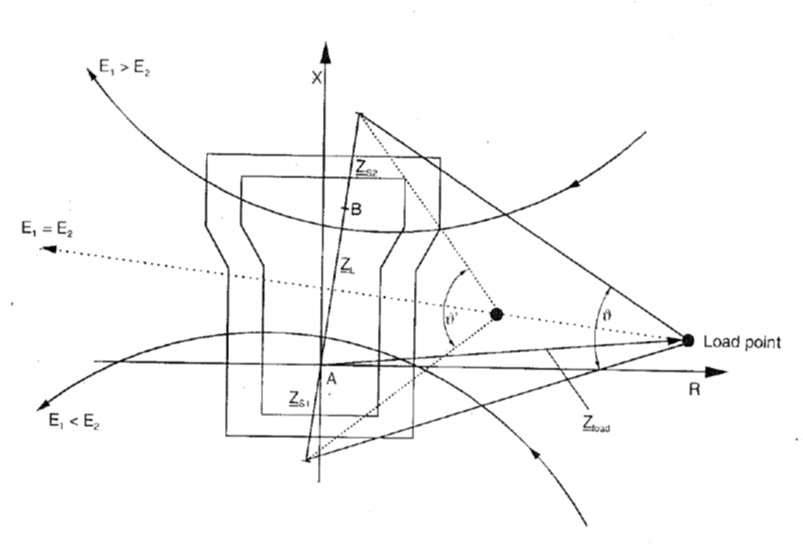
Tripping during power swing or pole slipping may be blocked by the power swing blocking (PSB) feature of distance protection.
PSB mode of operation is based on the fat that impedance immediately jumps from operating point to short circuit impedance inside distance relay characteristic
Conversely during a power swing, the impedance vector exhibits a steady progression. Its rate of change corresponds to power swing frequency of the system
By measurement of dZ/dt or DeltaZ/Deltat and comparison with a thresh hold it is possible to distinguish between short circuits and power swings
Typical measurement method is to determine elapsed time by impedance vector to pass through a zone limited by two impedance characteristics or blinders for which power swing characteristics zone is available in distance relay—say Zone 3 & Zone P
The power swing characteristics encloses the PSB start characteristics with a fixed distance of Delta Z (Delta R & Delta X)

The time will be shorter if power swing is faster
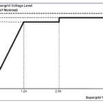
To detect large power swing frequencies the setting of Delta Z would be high and setting of Delta t would be small. Typical settings are
Delta Z =10 to 20 % Of Start Zone Impedance (Zone 3 if used for PSB)
Delta t = 20 to 40 milli-sec
With above settings power swings from 2 to 3 Hz can be detected