6. Voltage Flicker
The variations range from 0.1% to 7% of nominal voltage with frequencies less than 25 Hz. Subsequently, the most important effect of this power quality problem is the variation in the light output of various lighting sources, commonly termed as Flicker. This is the impression of instability of the visual sensation brought about by a light stimulus, whose luminance fluctuates with time.
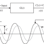
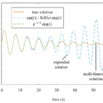
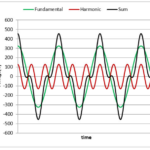
6.1 Illustration:
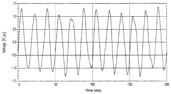
Figure 1: Voltage Fluctuations
Voltage fluctuation and light flicker are technically two distinct terms, but have been erroneously referred to the same meaning. Aggravating the confusion is the use of the expression “voltage flicker”, which does not actually exist, even though it is often heard.
Nevertheless, voltage fluctuation and flicker are closely related to each other. This is because flicker is derived from the impact of voltage fluctuation on lighting intensity due to large loads that have rapidly changing active and reactive power demand. In fact, voltage variations as low as 0.5% could result in perceptible light flicker if the frequencies are in the range of 6 to 8 Hz
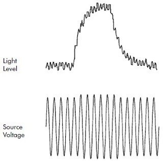
In other words, voltage fluctuation is the response of the power system to fast changing loads. On the other hand, light flicker is the response of the lighting system to such load variations as observed by the human eye.
Moreover, International standards have been developed for characterizing the voltage fluctuations based on the potential effects on lighting and the human perception of the lighting variations.
6.2 Sources and Causes
Equipment or devices that exhibit continuous, rapid load current variations (mainly in the reactive component) can cause voltage fluctuations and light flicker. Normally, these loads have a high rate of change of power with respect to the short-circuit capacity at the point of common coupling. Examples of these loads include:
- Electric arc furnaces
- Static frequency converters
- Cycloconverters
- Rolling mill drives
- Main winders
- Large motors (starting)
Similarly, small power loads such as welders, power regulators, boilers, cranes and elevators, to name a few, may cause voltage fluctuation and flicker depending on the Electrical system where they are connected.
Other causes include, but not limited to the following:
- Capacitor switching, Transformer On-Load Tap Changers (OLTC), Step Voltage Regulators and other devices that alter the inductive component of the source impedance.
- Variations in Generation capacity, particularly intermittent types (e.g. wind turbines).
- Low frequency voltage inter harmonics.
Furthermore, loose connections may also result to voltage fluctuations and flicker. Lightly loaded loose connections may cause flickers for longer periods as compared to heavily loaded ones that quickly burn out.
6.3 Effects
Flicker is considered the most significant effect of voltage fluctuation because it can affect the production environment by causing personnel fatigue and lower work concentration levels. In addition, voltage fluctuations may subject electrical and electronic equipment to detrimental effects that may disrupt production processes with considerable financial costs.
Other effects of voltage fluctuation include the following:
- Nuisance tripping due to malfunction of relays and contactors.
- Unwanted triggering of UPS units to switch to battery mode.
- Problems with some sensitive electronic equipment, which require a constant voltage (i.e. Medical laboratories).
7. Mitigation equipment and techniques
7.1 Dedicated circuit
The request for a dedicated circuit has always been a source of challenge in engineering offices. The ideal dedicated circuit will have, within reason, the lowest possible impedance. This is true because computers draw higher instantaneous currents during turn-on. To achieve this, the source of the circuit should theoretically be as close to the building service entrance as possible. However, it is not safe to assume that this will provide disturbance-free power, and in many cases the reverse is true, because transient spikes are traveling waves and the electronic devices should be as far away from the source of transients as possible. Thus, the point of connection of the “dedicated circuit” is a judgment call. Also, in a typical industrial plant of several million square feet, it is just not practical to run dedicated circuits to each of several hundred computers, terminals, and other electronic devices.
7.2 Shielded isolation transformer
Next to the dedicated circuit, the Shielded Isolation Transformer is the most popular power conditioner. Grounding the secondary of the delta isolation transformer provides the computer with a clean, noise free ground. Most power conditioner manufactures agree this is among the most important factors in providing a trouble-free power environment. The shielded isolation transformer also provides excellent common mode noise rejection, because of the low capacitance between the primary to secondary. There is no magnetic coupling, because common mode voltages do not impress any line-to-line or line- to-neutral voltages across the primary windings.
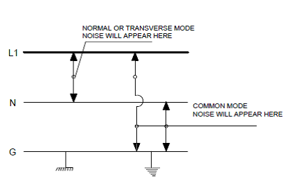
The shield, which usually consists of a foil wrapping of conducting non-magnetic material, conducts the electrostatic charge around the primary winding to ground, preventing it from coupling with the secondary, while providing greater than 300-to-1 common mode noise reduction.
Isolation transformer shields are generally ineffective in rejecting transverse (normal) mode transient, although there is some attention. Transverse mode transients or noise (unlike common mode) do impress a voltage across the primary windings. The isolation transformer is also useless in protecting against surges, sags, dips, and variations in steady state voltage. The shielded isolation transformer is often used in tandem with voltage regulators, transient suppressors, and other devices and power conditioners, because it offers excellent common mode noise rejection and a clean ground.
7.3 Voltage regulators
Constant Voltage Transformers (CVT) using Ferro resonant technologies are one of the most popular types of voltage regulators. These devices utilize a Ferro resonant circuit consisting of a capacitor in series with a transformer coil. The saturated core provides immunity to input voltage variations. Because of the saturated core, secondary voltage remains fairly constant, in spite of changes in primary voltages. As a result, this device takes virtually no time to respond. One common use is to power the primary logic motherboard in an adjustable speed drive from a CVT, to help isolate it from voltage variations.
However, these devices are known to have high impedances and to be sensitive to changes in load. Therefore, high inrush loads such as switching power supplies can produce transients and noise on the output. When electrostatic shielding and special transformer geometries are used, Ferro resonant devices can provide excellent common mode noise rejection.
7.4 Transient suppressors
Transverse-mode transient spikes are voltage spike between line conductors. These are produced by the power system through switching, SCR commutation action, faults, and grounds. As mentioned earlier, the spike is generally the first few half cycles of the leading edge of an oscillating overvoltage. Probably the least expensive, although not the most effective, way to remove these over voltages is through surgery, simply cutting them off or clipping them. This is the least understood and most misapplied technique.
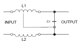
Probably the most common low voltage (120 volts), transient suppressor is the Metal Oxide Varistor (MOV), which is usually fast enough to clamp most transients. Silicon avalanche diodes are used to achieve very fast (5 nanoseconds) clamping. The use of surge suppressors, capacitors, and LC filters to eliminate spikes and their accompanying noise is fairly simple and straight forward.
Keep in mind that, in general, these devices only clip the spikes to ± several hundred volts peak-to-peak, which can still cause problems for PCs and other electronic equipment.
One of the disadvantages of transient suppressors is that they pump transients to ground, converting a line problem to a ground potential problem. This can effectively convert a transverse mode problem to a common mode problem. Surge suppressors and lightning arrestors should always be separated from the computer or electronic device ground by an isolation transformer.
One very unusual and highly accurate “active tracking” filter senses the instantaneous sine wave voltage at any point in the cycle. The LC circuit limits the maximum voltage that can appear at the output of the filter. This filter begins to limit the deviation from the true instantaneous sine-wave voltage whenever the deviation becomes greater than ± 2 volts. When a voltage deviation is sensed, the unit switches the capacitor leg into the circuit, providing full filtering in less than 5 ns. Not only are spikes clipped very effectively, but the trailing notches are also “filled in” by the energy stored in the filter’s capacitance, which cannot be done by simple clamping devices.
These devices are available in receptacle models and hard-wired models, both single and three phase, in 120, 240, and 480 volt styles.
7.5 Uninterruptible power supply
Where a high degree of voltage regulation and total isolation from sags, dips, surges, and transient is required, an Uninterruptible Power Supply (UPS) may be used. UPS provides standby capacity for power fails and short outages and provides constant frequency. As a minimum, the UPS allows for orderly shutdown of computer equipment without risk of equipment damage or memory loss. Since UPSs are solid-state devices, they often require power conditioners themselves. A surge suppressor or other type of transient remover is necessary to prevent damage to their solid-state components. Depending on the KVA rating, a UPS unit can take up a great deal of space, and because of the batteries, care must be taken in selecting a battery room that can handle the structural load.
Perhaps the biggest disadvantage of using UPS is their high impedance and the high voltage drops associated with that impedance. This is of particular importance with switching power supplies, which themselves are noise generators. Sometimes it is necessary to size these systems for one or more multiples of normal operating current, to compensate for the resulting voltage drop. Since UPS are more expensive than other forms of power conditioners, especially when they are required to be oversized, the user should be sure they are really needed before making the investment.
There are three major UPS versions.
- Continuous service batteries. Direct current from the batteries is inverted to AC to power the UPS changes utility power to direct current to charge a set of page computer.
- A standby type of UPS involves operating the computer on line power, but it switches to battery power in case of main power interruption. This can cause a very short (4 to16 ms) power dip to the load. The battery is continuously kept charged by the battery charger.
- A reverse transfer UPS offers additional security, because the computer load is transferred to utility power if the UPS is temporarily overloaded or when a malfunction occurs within the UPS itself.
It is important to realize that the output distortion of the UPS for a given load depends on the UPS design and output impedance. If the load distorts the power supplied by the Ups, then the power fed to the loads will not be truly “clean.” Most UPS manufacturers specify the output distortion of their equipment; 5% total harmonic distortion (THD) is typical. However many manufacturers add a disclaimer, such as “Based on Linear loads” or “for Reactive and Inductive loads” such a disclaimer means that the THD only applies under linear load conditions. Before purchasing any UPS, make certain that it is capable of supplying the actual types of nonlinear loads to be connected.
Less expensive ride-through of up to half a second can be achieved when using adjustable speed drives by adding capacitors to the DC bus, providing the power supply is suitably sized. This approach was recently used effectively when applied to a system of HVAC fans in a large industrial building.
Other Flicker Mitigation Techniques
In some cases, the strategies stated below can reduce flicker problems:
- Use isolating transformers to separate the supply terminal that feeds the fluctuating loads, especially from the lighting power supply.
- Connect the loads to a phase and feed the lighting systems from the non-disturbed phases. This solution is applicable for single-phase loads connected at the low voltage or medium voltage systems.
- Operate flicker-producing loads at a time when they cannot disturb people. For example, operating the load at night since most people are not working at this time.
- Implement changes in the operating practice and/or equipment design to minimize voltage fluctuations. An example is limiting arc furnace transformer taps during the initial meltdown period, when flicker is more perceptible. This reduces the operating voltage and decrease PST during these intervals.
- Lower the motor starting or inrush current to reduce voltage variations (e.g. soft start devices).
- Supplying the fluctuating loads from a decoupled source of the utility system (e.g. diesel–electric group).
8. Conclusion
The intent of this chapter has been to establish that the selection and application of power conditioning equipment is a complex issue with no simple solution. Sometimes even the experts disagree in their basic philosophies. They disagree on the nature of the problem, and they disagree as to which technologies are best for solving the problem. Selection of power conditioning equipment requires an understanding of power system disturbances and the available technologies for eliminating them.
It is also important to understand the consequences and the cost of the downtime, unscheduled outages, and equipment damage. No conditioner should ever be applied to any piece of equipment without first consulting the manufacturer who knows for sure what types of disturbances are likely to damage or otherwise affect that particular brand of equipment.