Overhead lines are, in essence, air-insulated cables suspended from insulated supports with a power transfer capacity approximately proportional to the square of the line voltage. Overhead lines are cheaper in initial capital cost and are generally more economic than cable feeders. For the transmission of equivalent power at 11KV, a cable feeder would cost some five times the cost of a transmission line, at 132KV up to 8 times, and at 400Kv between 10 and 20 times. Such comparisons must, however, be treated in more depth since they must take into account rights of way, amenity, clearance problems, planning permissions associated with the unsightly nature of erecting bare conductors in rural and urban areas and ongoing operations and maintenance requirements.
Environmental Conditions
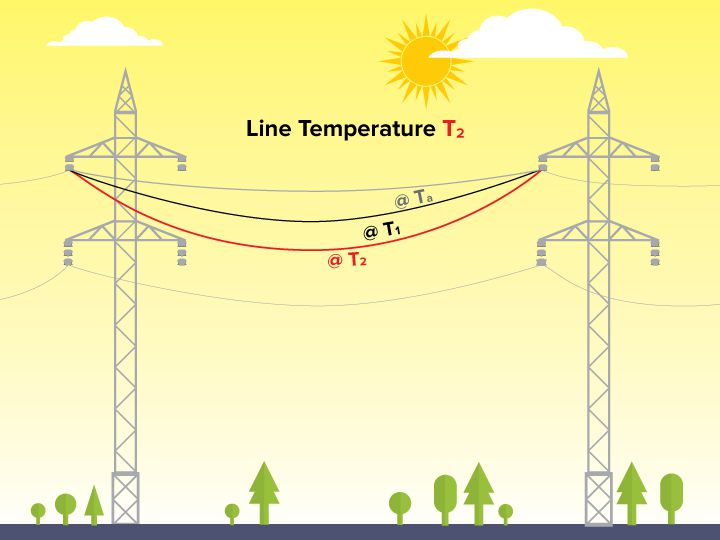
To match both the mechanical and electrical characteristics of the overhead line conductor to the environmental conditions, climatic details must first be collected and analysed.
- Temperature
- Wind velocity
- Solar radiation
- Rainfall
- Humidity
- Altitude
- Ice and snow
- Atmospheric pollution
- Soil Characteristics
- Lightning
- Seismic factor
- General loadings
Conductor Selection:
The selection of the most appropriate conductor size at a particular voltage level must take into account both technical and economic criteria as listed below:
- The maximum power transfer capability must be in accordance with system requirements.
- The conductor cross-sectional area should be such as to minimize the initial capital cost and the capitalized cost of the losses.
- The conductor should conform to standard sizes already used elsewhere on the network to minimize spares holdings and introduce a level of standardization.
- The conductor thermal capacity must be adequate
- The conductor diameter or bundle size must meet recognized standards for radio interference and corona discharge.
- The conductor must be suitable for the environmental conditions and confirm to constructional methods understood in the country involved.
Types of conductor
There are four major types of overhead conductors used for electrical transmission and distribution.
- AAC – All Aluminum Conductor
- AAAC – All Aluminum Alloy Conductor
- ACSR – Aluminum Conductor Steel Reinforced
- ACAR – Aluminum Conductor Aluminum-Alloy Reinforced
AAC – All Aluminum Conductors
This type is sometimes also referred as ASC (Aluminum Stranded Conductor). It is made up of strands of EC grade or Electrical Conductor grade aluminum. AAC conductor has conductivity about 61% IACS (International Annealed Copper Standard). Despite having a good conductivity, because of its relatively poor strength, AAC has limited use in transmission and rural distribution lines. However, AAC can be seen in urban areas for distribution where spans are usually short but higher conductivity is required.
AAAC – All Aluminum Alloy Conductors
These conductors are made from aluminum alloy 6201 which is a high strength Aluminum-Magnesium-Silicon alloy. This alloy conductor offers good electrical conductivity (about 52.5% IACS) with better mechanical strength. Because of AAAC’s lighter weight as compared to ACSR of equal strength and current capacity, AAAC may be used for distribution purposes. However, it is not usually preferred for transmission. Also, AAAC conductors can be employed in coastal areas because of their excellent corrosion resistance.
ACSR – Aluminum Conductor Steel Reinforced
ACSR consists of a solid or stranded steel core with one or more layers of high purity aluminum (aluminum 1350) wires wrapped in spiral. The core wires may be zinc coated (galvanized) steel or aluminum coated (aluminized) steel. Galvanization or aluminization coatings are thin and are applied to protect the steel from corrosion. The central steel core provides additional mechanical strength and, hence, sag is significantly less than all other aluminum conductors. ACSR conductors are available in a wide range of steel content – from 6% to 40%. ACSR with higher steel content is selected where higher mechanical strength is required, such as river crossing. ASCR conductors are very widely used for all transmission and distribution purposes.
ACAR – Aluminum Conductor Aluminum-Alloy Reinforced
ACAR conductor is formed by wrapping strands of high purity aluminum (aluminum 1350) on high strength Aluminum-Magnesium-Silicon alloy (6201 aluminum alloy) core. ACAR has better electrical as well as mechanical properties than equivalent ACSR conductors. ACAR conductors may be used in overhead transmission as well as distribution lines.
Bundled Conductors
Transmission at extra high voltages (say above 220 kV) poses some problems such as significant corona loss and excessive interference with nearby communication lines when only one conductor per phase is used. This is because, at EHV level, the electric field gradient at the surface of a single conductor is high enough to ionize the surrounding air which causes corona loss and interference problems. The electric field gradient can be reduced significantly by employing two or more conductors per phase in close proximity. Two or more conductors per phase are connected at intervals by spacers and are called as bundled conductors. The image at right shows two conductors in bundled form per phase. Number of conductors in a bundled conductor is greater for higher voltages.
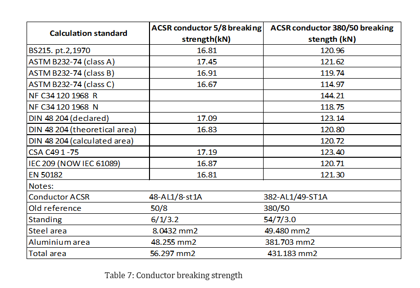
Conductor breaking strength
The calculation of conductor behavior under changing loading conditions (wind, ice ) and temperature is related to breaking strengths, and the design of fittings (tensions clamps, repair sleeves etc.) must also be related to these values. Hence, it is necessary in any overhead line specification to state clearly which standard calculated breaking strengths are to be based on in order to avoid disputes at a later date.
Calculated conductor breaking strengths according to some different standards:
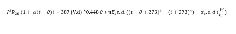 Where,