Power carrying Capacity:
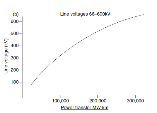
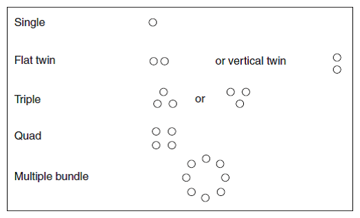
Approximate economic power transfer capacity trends for different line voltages based on power transfer being proportional to the square of the line voltage are given figure 1(a) and (b) for transmission voltages up to 500KV. In practice, the capacity will be limited over long distances by the conductor natural impedance (voltage regulation) as well as by conductor thermal capacity. Depending upon the required electrical load transfer, the number of overhead line conductors of a particular type used per phase may vary. Conductor configurations are shown in figure 2.
Therefore under the following specific tropical conditions (40°C ambient temperature, 0.894 m/s wind speed, 100 mW/ solar radiation and 30 °C temperature rise), the calculated ratings for typical ACSR twin conductors at 230 KV would be:
2 x 200 (nominal) – 1052 A (419 MVA)
2 x 300 (nominal) – 1296 A (419 MVA)
2 x 400 (nominal) – 1558 A (419 MVA)
2 x 500 (nominal) – 1742 A (419 MVA)
2 x 600 (nominal) – 1890 A (419 MVA)
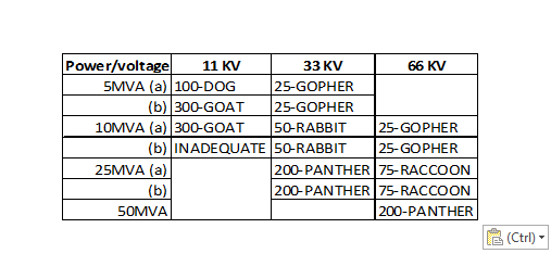 Table 8: Approximate conductor sizes (ACSR) for power transfer capabilities
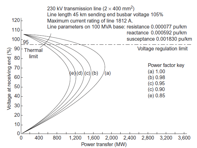
By the intersection of the regulation curves for, 0.9 power factor with either the thermal limit or the voltage regulation lines, whichever does not infringe the voltage or current limit specified for the line. It should be noted that adequate technical performance is usually judged upon the load flow under single circuit outage conditions. In comparison, economic loadings do not normally consider outages and are based on normal operating conditions.
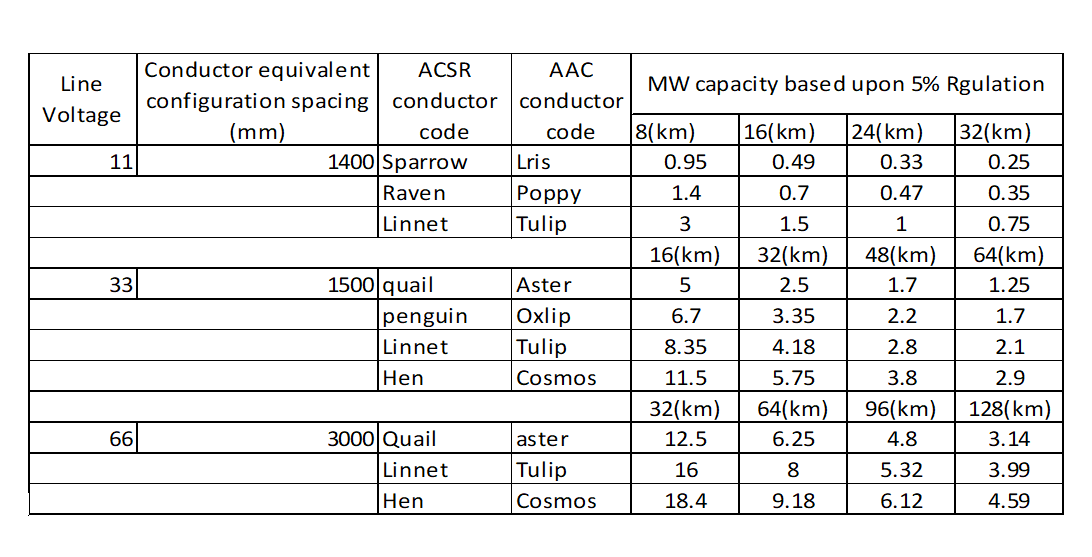
Table 9: Table of different conductors over different distances
Calculated ratings for typical ACSR conductors at lower voltage levels of 11, 33 and 66kV overhead lines using different conductors over different distances are given in table 9.
Corona Discharge
High voltage gradients surrounding conductors (above about 18KV/cm) will lead to a breakdown of the air in the vicinity of the conductor surface known as corona discharge. The effect is more pronounced at high altitudes. Generally, the breakdown strength of air is approximately 31kV peak/cm or 22kV rms/cm. This is a useful guide for the selection of a conductor diameter or conductor bundle arrangement equivalent diameter. Corona discharge and radio interference noise generated cause problems with the reception of radio communication equipment and adversely affect the performance of power line carrier signals.
At higher voltage levels, and certainly at voltages of 400KV and above interferences due to the corona effects can be the dominant factor in determining the physical size of the conductor rather than the conductor thermal rating characteristic. Increasing the conductor diameter may be necessary in order to reduce the surface stress to acceptable levels. Obviously, there is a limit with regard to the practical size, strength and handling capability for conductors.
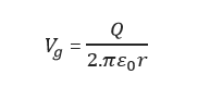
The surface voltage gradient may be determined from gauss’s theorem showing that an increase in radius or equivalent radius leads to a reduction in surface voltage gradient.
Where
![]() = Voltage surface gradient (Volts/cm)
= Voltage surface gradient (Volts/cm)
Q = surface charge per unit length (coulomb/m
r = equivalent radius of smooth conductor (cm)
![]() = permittivity of free space = 1/ (36π x ) (F/m)
= permittivity of free space = 1/ (36π x ) (F/m)
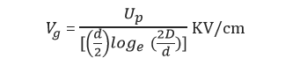
In practical terms this may also be expressed as follows:
Where
![]() = Voltage surface gradient (KV/cm)
= Voltage surface gradient (KV/cm)
![]() = Phase voltage (KV)
= Phase voltage (KV)
d = diameter of single conductor (cm)
D = diameter between phases for single phase line or equivalent spacing for three phase lines (cm)
For the three phase line configurations, ![]() are the spacing between the different phases r, y and b.
are the spacing between the different phases r, y and b.
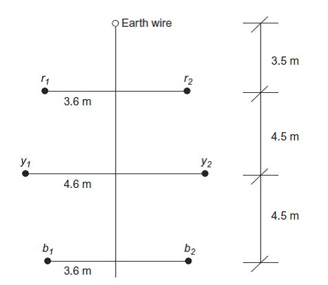
Consider a 33 KV single circuit Zebra ACSR line with conductor diameter 28.62 mm and spacing as shown in Figure 4.
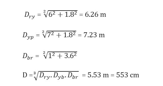
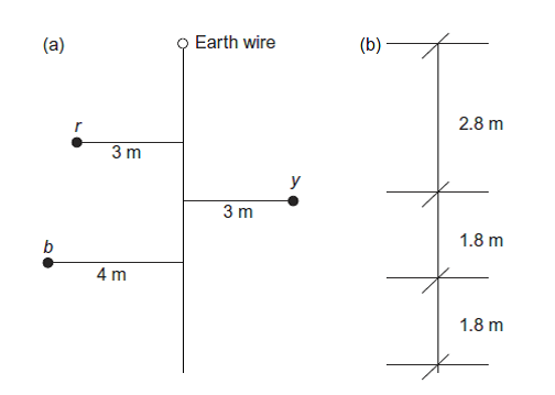
Figure 4: Corona discharge calculation 33 KV Zebra conductor spacing
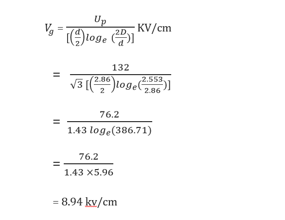
This is within the 18 KV criteria.
Radio frequency interference (RFI) noise is measured in decibels above 1 microvolt per meter (dB> 1 µ V/m ) from comparative equations of the form:
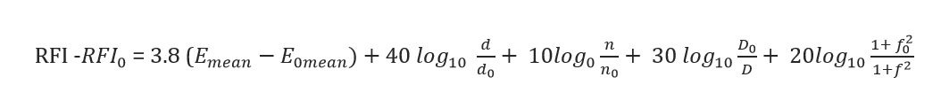
Where,
RIF = calculated radio noise (dB > 1m V/m)
![]() = Calculated mean voltage gradient (KV /cm)
= Calculated mean voltage gradient (KV /cm)
D = conductor diameter (cm)
n = (number of sub-conductors in bundle)
D = distance between phase and measuring antenna (m)
f = Frequency (Hz)
The suffix ‘0’refers to the same quantities obtained from measurements. Acceptable noise levels depend upon the quality of service required and is described in terms of an acceptable signal-to-noise or signal plus noise-to-noise.
Thus, if a signal has a field strength of 60DB > 1 µ V/m and a fairly satisfactory reception is required then the noise from the adjacent overhead line should not exceed 60-22 =38 dB> 1µ V/m. Audible noise is generally not considered to be controlling factor at voltage levels below 500 KV.
Overhead Line Calculation Example:
If we wish to transfer 40MVA over a distance of 70 Km, then we can calculate the conductor and tower size using the simple hand calculations given below. Such calculations are a useful check to the more normally used computer generated solutions and allow an understanding of the basic principles involved
Assume Lynx ACSR overhead line under the following tropical conditions operating at 33kV.
Maximum operating temperature 75°C
Maximum ambient air temperature 40°C (temperature rise = 35°C)
Lynx conductor max resistance 0.1441 ohms/km
Lynx conductor diameter 19.53 mm
Emissivity 0.6
Solar absorption coefficient 0.8
Solar radiation intensity 1000 W/
Wind Velocity 1 mph = 0.447 m/s
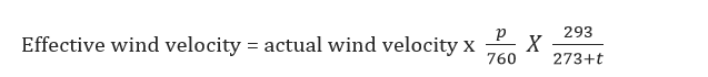
= 0.447 x (760/760) x (293/313) = 0.418 m/s
=41.8 cm/s (assuming normal atmospheric pressure)

= 699 A
The conductor thermal rating capability is first determined, ignoring any voltage drop considerations, by comparing the 699 A load current requirement and the rating of the conductor derived from the heat balance equation.
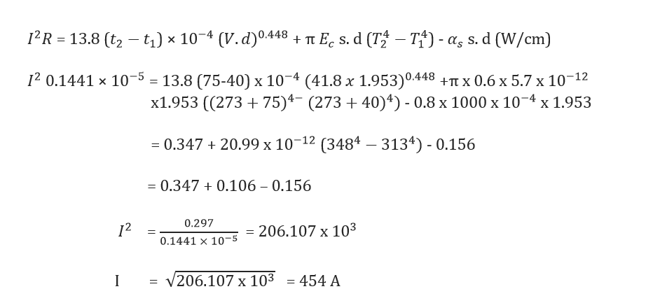
Consider 2 runs of conductor type is therefore more than adequate on thermal considerations for the load required.

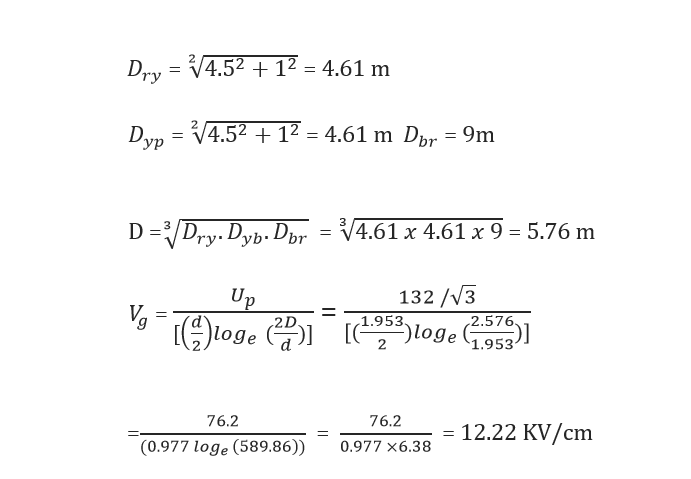
Which is within the 18 KV / cm criteria, and Lynx conductor is therefore acceptable from both a corona and current carrying capacity point of view.
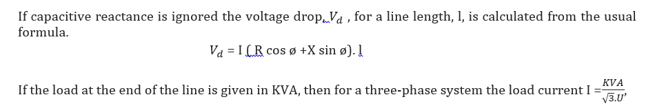
where U equals the line voltage in KV.
The value of (R cos + X sin ) is approximately constant for overhead line configurations with conductor sizes above 150![]() to 200
to 200![]() . Therefore very large conductors are necessary to improve any voltage drop problems if such conductor sizes prove to be inadequate. In such circumstances, consideration should be given to increasing the transmission voltage level.
. Therefore very large conductors are necessary to improve any voltage drop problems if such conductor sizes prove to be inadequate. In such circumstances, consideration should be given to increasing the transmission voltage level.
It is useful to introduce the concept of allowable KVA km for a given voltage drop for a variety of overhead line configurations and different conductors. For a 10% voltage drop then,

With length, l, in km
Tables may be prepared based on this equation for different conductors at different pfs giving the allowable KVA km for a given % voltage drop.