Relay Coordination Study – Introduction
Relay Coordination Study is performed to ensure correct protection selectivity and grading between relays. This Relay Coordination Study helps avoid unnecessary tripping and ensures reliable fault clearance.
What is Relay Coordination Study?
Relay coordination is the arrangement of protection settings such that the protective device closest to the fault operates first. Backup devices operate only if the primary protection fails. This selective operation limits the fault impact and reduces unnecessary interruptions.
Relay coordination is commonly applied in:
Distribution networks
Industrial power systems
Substations and switchgear installations
Feeder Protection Devices
The commonly used overcurrent protection devices in feeder protection are:
Fuses
Relays with circuit breakers (shunt trip)
Low voltage circuit breakers with built-in trip units
In overhead distribution systems, automatic reclosers and sectionalisers are also used.
Fuse Protection
A fuse is the simplest form of overcurrent protection. It operates by melting when the current exceeds its rated value. For high fault currents, fuses operate very quickly, thereby limiting the fault energy.
Advantages
Simple and reliable
No maintenance required
Low cost
Fast operation for heavy faults
Limitations
Coordination is difficult due to fixed characteristics
Replacement required after fault operation
Limited sensitivity to earth faults
Can cause single phasing in three-phase systems
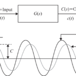
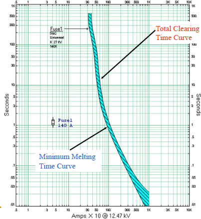
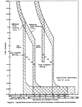
Fuse Time–Current Curve
Fuse behaviour is represented using current–time (I–t) curves. These curves show:
Minimum melting time
Total clearing time
These characteristics are used during coordination studies to ensure proper time grading with other protection devices.
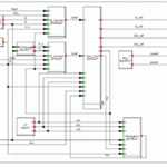
LV CIRCUIT BREAKER
Low Voltage Circuit Breakers
Low voltage circuit breakers provide both manual switching and automatic fault interruption. In the event of a fault, the breaker opens based on the magnitude of current and the characteristics of its trip unit.
The trip unit determines when the circuit breaker operates.
Thermo-Magnetic Trip Unit
This type of trip unit consists of:
A thermal element for overload protection with time delay
A magnetic element for short-circuit protection with instantaneous operation
Thermo-magnetic trip units are widely used in standard LV systems.
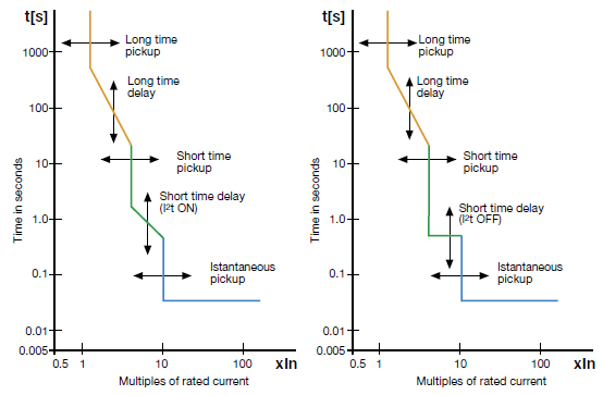
Electronic Trip Unit (LSIG)
Electronic trip units use electronic sensing and control for improved accuracy and flexibility. These trip units provide multiple protection functions, such as:
Long-time overcurrent protection
Short-time overcurrent protection
Instantaneous overcurrent protection
Ground fault protection
These functions are commonly referred to as LSIG protection.
Importance of LV Level
Proper coordination of LV protection devices ensures:
Selective isolation of faults
Reduced equipment damage
Improved system reliability
Enhanced safety for operating personnel
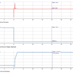
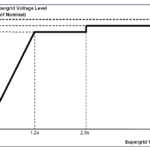
Characteristics of thermo-magnetic trip unit
Conclusion
Relay coordination plays a vital role in the safe and reliable operation of electrical power systems. Part 1 has explained the basic feeder protection devices, including fuses and low voltage circuit breakers, along with their operating characteristics.