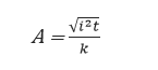
Where,
A is the minimum cross-sectional area of the cable ![]()
i is the prospective short circuit current (A)
t is the duration of the short circuit (s)
k is a short circuit temperature rise constant
The temperature rise constant is calculated based on the material properties of the conductor and the initial and final conductor temperatures.
For copper cables:
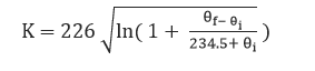
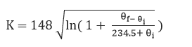
Where,
![]() and are the initial and final conductor temperatures respectively.
and are the initial and final conductor temperatures respectively.
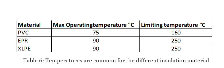
The following temperatures are common for the different insulation materials
Enquiry preparation and order specification:
- Low and medium voltage cable enquiry shall be prepared.
- For package always use 3.5 core cables
- Specify only extruded cables
- Cable estimation for each length shall be accurately with 5% margin on higher side.
- With order specification, depending on length, especially for higher size of cables drum length schedule can be given
- Also changes taken place during the course of engineering shall be accounted.
Example 1:
Motor rating = 90KW
Full load current = 157
De-rating factor:
- Rating factor for variation in depth of laying in ground = 0.97
- Group rating factor for multi-core formation and laid direct in the ground =0.48
- Rating factor for variation in ground temperature = 0.94
- Rating factor for variation in thermal resistivity of soil = 1.0
De-rating factor for cable is laid in air and also in trench = 0.97 x 0.48 x 094 x 1.0
= 0.44
Therefore, the cable should have current rating of 157 A
3.5 core x 185 Sq.mm cable has current rating = 200 A in duct
We are using 2 runs of 3.5 C x 185 Sq.mm cable
The total capacity = 2 x 200 = 400 A (which is more than 356.82 A)
Thus 2 runs of 3.5C x 185 Sq. mm cable are adequate.
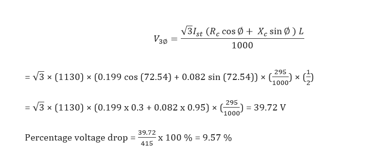
Full load current = 157 A
(Starting p.f = 0.3) = 1130A
Phase = 72.54°
We have selected 2 runs of 3.5 C x 185 ![]()
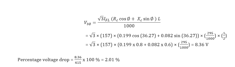
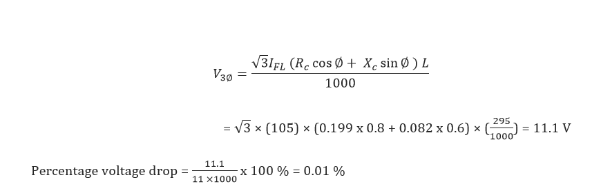
R = 0.199 Ω/km
X = 0.082 Ω/km
Power factor cos ⍬ = 0.8
⍬ = 36.27°
Voltage drop during starting: