Three Phase Fault Example
Per unit analysis can be used to calculate system three phase fault levels and the current distributions. To gain a better understanding, it is worth running through the typical steps required to solve a fault calculation problem.
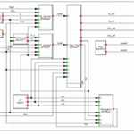
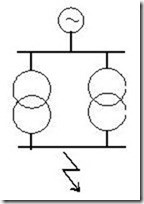
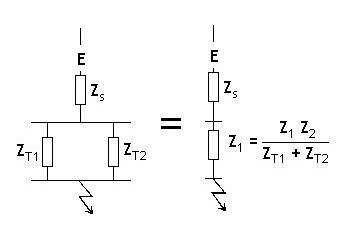
Given the system single line diagram, construct and simplify the per unit impedance diagram.
The fault level at the point under consideration is given by:

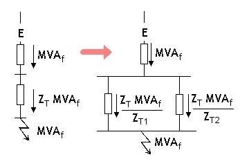
Having calculated the fault flow in each branch, it is then relatively simple to find the current distribution using:
![]()
Example:
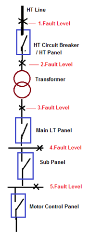
Calculate Fault current at each stage of following Electrical System SLD having details of.
- Main Incoming HT Supply Voltage is 6.6 KV.
- Fault Level at HT Incoming Power Supply is 360 MVA.
- Transformer Rating is 2.5 MVA.
- Transformer Impedance is 6%.
Calculation:
- Let’s first consider Base KVA and KV for HT and LT Side.
- Base KVA for HT side (H.T. Breaker and Transformer Primary) is 6 MVA
- Base KV for HT side (H.T. Breaker and Transformer Primary) is 6.6 KV
- Base KVA for LT side (Transformer Secondary and down Stream) is 2.5 MVA
- Base KV for LT side (Transformer Secondary and down Stream) is 415V
Fault Level at HT Side (Up to Sub-station):
(1)Fault Level from HT incoming Line to HT Circuit Breaker
- HT Cable used from HT incoming to HT Circuit Breaker is 5 Runs , 50 Meter ,6.6KV 3 Core 400 sq.mm Aluminum Cable , Resistance of Cable 0.1230 Ω/Km and Reactance of Cable is0.0990 Ω/Km.
- Total Cable Resistance(R) = (Length of Cable X Resistance of Cable) / No of Cable.
- Total Cable Resistance=(0.05X0.1230) / 5
- Total Cable Resistance=0.001023 Ω
- Total Cable Reactance(X) = (Length of Cable X Reactance of Cable) / No of Cable.
- Total Cable Reactance=(0.05X0.0990) / 5
- Total Cable Reactance =0.00099 Ω
- Total Cable Impedance (Zc1)=√(RXR)+(XxX)
- Total Cable Impedance (Zc1)=0.0014235 Ω——–(1)
- U Reactance at H.T. Breaker Incoming Terminals (X Pu)= Fault Level / Base KVA
- U Reactance at H.T. Breaker Incoming Terminals (X Pu)= 360 / 6
- Reactance at H.T. Breaker Incoming Terminals(X Pu)= 0.01666 PU——(2)
- Total Impedance up to HT Circuit Breaker (Z Pu-a)= (Zc1)+ (X Pu) =(1)+(2)
- Total Impedance up to HT Circuit Breaker(Z Pu-a)=0.001435+0.01666
- Total Impedance up to HT Circuit Breaker (Z Pu-a)=0.0181 Ω.——(3)
- Fault MVA at HT Circuit Breaker= Base MVA / Z Pu-a.
- Fault MVA at HT Circuit Breaker= 6 / 0.0181
- Fault MVA at HT Circuit Breaker= 332 MVA
- Fault Current = Fault MVA / Base KV
- Fault Current = 332 / 6.6
- Fault Current at HT Circuit Breaker = 50 KA
(2) Fault Level from HT Circuit Breaker to Primary Side of Transformer
- HT Cable used from HT Circuit Breaker to Transformer is 3 Runs , 400 Meter ,6.6KV 3 Core 400 sq.mm Aluminum Cable , Resistance of Cable 0.1230 Ω/Km and Reactance of Cable is0.0990 Ω/Km.
- Total Cable Resistance(R)= (Length of Cable X Resistance of Cable) / No of Cable.
- Total Cable Resistance=(0.4X0.1230) / 3
- Total Cable Resistance=0.01364 Ω
- Total Cable Reactance(X)= (Length of Cable X Reactance of Cable) / No of Cable.
- Total Cable Reactance=(0.4X0.0990) / 5
- Total Cable Reactance =0.01320 Ω
- Total Cable Impedance (Zc2)=√(RXR)+(XxX)
- Total Cable Impedance (Zc2)=0.01898 Ω——–(4)
- U Impedance at Primary side of Transformer (Z Pu)= (Zc2 X Base KVA) / (Base KV x Base KVx1000)
- U Impedance at Primary side of Transformer (Z Pu)= (0.01898X6) /(6.6×6.6×1000)
- U Impedance at Primary side of Transformer (Z Pu)= 0.0026145 PU——(5)
- Total Impedance(Z Pu)=(4) + (5)
- Total Impedance(Z Pu)=0.01898+0.0026145
- Total Impedance(Z Pu)=0.00261——(6)
- Total Impedance up to Primary side of Transformer (Z Pu-b)= (Z Pu)+(Z Pu-a) =(6)+(3)
- Total Impedance up to Primary side of Transformer (Z Pu-b)= 0.00261+0.0181
- Total Impedance up to Primary side of Transformer (Z Pu-b)=0.02070 Ω.—–(7)
- Fault MVA at Primary side of Transformer= Base MVA / Z Pu-b.
- Fault MVA at Primary side of Transformer = 6 / 0.02070
- Fault MVA at Primary side of Transformer= 290 MVA
- Fault Current = Fault MVA / Base KV
- Fault Current = 290 / 6.6
- Fault Current at Primary side of Transformer= 44 KA
(3) Fault Level from Primary Side of Transformer to Secondary side of Transformer:
- Transformer Rating is 2.5 MVA and Transformer Impedance is 6%.
- % Reactance at Base KVA = (Base KVA x % impedance at Rated KVA) / Rated KVA
- % Reactance at Base KVA = (2.5X6)/2.5
- % Reactance at Base KVA =6%
- Reactance of the Transformer(Z Pu) =% Reactance /100
- Reactance of the Transformer(Z Pu)= 6/100=0.06 Ω—–(8)
- Total P.U. impedance up to Transformer Secondary Winding(Z Pu-c)=(Z Pu)+(Z Pu-b)=(7)+(8)
- Total P.U. impedance up to Transformer Secondary Winding(Z Pu-c)=0.06+0.02070
- Total P.U. impedance up to Transformer Secondary Winding(Z Pu-c)=0.0807 Ω—–(9)
- Fault MVA at Transformer Secondary Winding = Base MVA / Z Pu-c
- Fault MVA at Transformer Secondary Winding = 2.5/0.0807
- Fault MVA at Transformer Secondary Winding =31 MVA
- Fault Current = Fault MVA / Base KV
- Fault Current = 31 / (1.732×0.415)
- Fault Current at Transformer Secondary Winding = 43 KA
Fault Level at LT Side (Sub-station to downstream):
(4) Fault Level from Transformer Secondary to Main LT Panel
- LT Cable used from Transformer Secondary to Main LT Panel is 13 Runs , 12 Meter , 1KV, 3.5C x 400 Sq.mm Aluminum Cable , Resistance of Cable 0.1230 Ω/Km and Reactance of Cable is0.0618 Ω/Km.
- Total Cable Resistance(R)= (Length of Cable X Resistance of Cable) / No of Cable.
- Total Cable Resistance=(0.012X0.1230) / 13
- Total Cable Resistance=0.00009 Ω
- Total Cable Reactance(X)= (Length of Cable X Reactance of Cable) / No of Cable.
- Total Cable Reactance=(0.012X0.0618) / 13
- Total Cable Reactance =0.00006 Ω
- Total Cable Impedance (Zc3)=√(RXR)+(XxX)
- Total Cable Impedance (Zc3)=0.00011 Ω——–(10)
- U Impedance at Main LT Panel (Z Pu)= (Zc3 X Base KVA) / (Base KV x Base KVx1000)
- U Impedance at Main LT Panel (Z Pu)= (0.00011X2.5×1000)/(0.415×0.415X1000)
- P P.U Impedance at Main LT Panel (Z Pu)= 001601 Ω ——(11)
- Total Impedance up to Main LT Panel(Z Pu-d)= (Zc3)+ (Z Pu-c) =(11)+(9)
- Total Impedance up to Main LT Panel (Z Pu-d)= 0.001601 +0.0807
- Total Impedance up to Main LT Panel (Z Pu-d)=0.082306 Ω.——(12)
- Fault MVA at Main LT Panel= Base MVA / Z Pu-a.
- Fault MVA at Main LT Panel = 2.5 / 0.082306
- Fault MVA at Main LT Panel= 30 MVA
- Fault Current = Fault MVA / Base KV
- Fault Current = 30 / (1.732X0.415)
- Fault Current at Main Lt Panel = 42 KA
(5) Fault Level from Main LT Panel to Sub Panel:
- LT Cable used from Main LT Panel to Sub Panel is 2 Runs , 160 Meter , 1KV, 3.5C x 400 Sq.mm Aluminum Cable , Resistance of Cable 0.1230 Ω/Km and Reactance of Cable is0.0618 Ω/Km.
- Total Cable Resistance(R)= (Length of Cable X Resistance of Cable) / No of Cable.
- Total Cable Resistance=(0.160X0.1230) / 2
- Total Cable Resistance=0.008184 Ω
- Total Cable Reactance(X)= (Length of Cable X Reactance of Cable) / No of Cable.
- Total Cable Reactance=(0.160X0.0618) / 2
- Total Cable Reactance =0.004944 Ω
- Total Cable Impedance (Zc4)=√(RXR)+(XxX)
- Total Cable Impedance (Zc4)=0.0095614 Ω——–(13)
- U Impedance at Sub Panel (Z Pu)= (Zc4 X Base KVA) / (Base KV x Base KVx1000)
- U Impedance at Sub Panel (Z Pu)= (0.0095614 X2.5×1000)/(0.415×0.415X1000)
- P P.U Impedance at Sub Panel (Z Pu)= 13879 Ω ——(14)
- Total Impedance up to Sub Panel (Z Pu-e)= (Zc4)+ (Z Pu-d) =(14)+(12)
- Total Impedance up to Sub Panel (Z Pu-e)= 0.13879 +0.082306
- Total Impedance up to Sub Panel (Z Pu-e)=0.2211 Ω.——(15)
- Fault MVA at Sub Panel = Base MVA / Z Pu-a.
- Fault MVA at Sub Panel = 2.5 / 0.2211
- Fault MVA at Sub Panel = 11 MVA
- Fault Current = Fault MVA / Base KV
- Fault Current = 11 / (1.732X0.415)
- Fault Current at Sub Panel= 16 KA
(6) Fault Level from Sub Panel to Motor Control Panel:
- LT Cable used from Sub Panel to Motor Control Panel is 6 Runs , 150 Meter , 1KV, 3.5C x 400 Sq.mm Aluminum Cable , Resistance of Cable 0.1230 Ω/Km and Reactance of Cable is0.0739 Ω/Km.
- Total Cable Resistance(R)= (Length of Cable X Resistance of Cable) / No of Cable.
- Total Cable Resistance=(0.150X0.1230) / 6
- Total Cable Resistance=0.003075 Ω
- Total Cable Reactance(X)= (Length of Cable X Reactance of Cable) / No of Cable.
- Total Cable Reactance=(0.150X0.0739) / 6
- Total Cable Reactance =0.0018475 Ω
- Total Cable Impedance (Zc5)=√(RXR)+(XxX)
- Total Cable Impedance (Zc4)=0.003587 Ω——–(16)
- U Impedance at Motor Control Panel (Z Pu)= (Zc5 X Base KVA) / (Base KV x Base KVx1000)
- U Impedance at Motor Control Panel (Z Pu)= (0.003587 X2.5×1000)/(0.415×0.415X1000)
- P P.U Impedance at Motor Control Panel (Z Pu)= 05207 Ω ——(17)
- Total Impedance up to Motor Control Panel (Z Pu-f)= (Zc5)+ (Z Pu-e) =(17)+(15)
- Total Impedance up to Motor Control Panel (Z Pu-e)= 0.13879 +0.2211
- Total Impedance up to Motor Control Panel (Z Pu-e)=0.27317 Ω.——(15)
- Fault MVA at Motor Control Panel= Base MVA / Z Pu-a.
- Fault MVA at Motor Control Panel = 2.5 / 0.27317
- Fault MVA at Motor Control Panel = 9 MVA
- Fault Current = Fault MVA / Base KV
- Fault Current = 9 / (1.732X0.415)
- Fault Current at Motor Control Panel= 13 KA